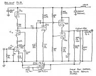
Grant RIAA Phono with 12ax7/ecc83
I received this phono amp as a gift from a friend who had given up on trying to fix it. I was able to repair it and was surprised at the sound quality.
I have a power schematic that rates the B+ at 250 but the actual power supply in the amp delivers a solid 340 volts. It does appear to be all original too...
It uses 3 ecc83's per channel and has very nice sound despite the seemingly incorrect B+.
There is no gain problems, but a bit of humm when I use it with MC especially.
I was just about to adjust the 470 Ohm and 47K input resistors to match for cartridge impedance but would like someone else to look at the circuit first. I want to do this without changing the characteristics of the RIAA curve of course.
Thanks
soulemerchant
I received this phono amp as a gift from a friend who had given up on trying to fix it. I was able to repair it and was surprised at the sound quality.
I have a power schematic that rates the B+ at 250 but the actual power supply in the amp delivers a solid 340 volts.
It does appear to be all original too...It uses 3 ecc83's per channel and has very nice sound despite the seemingly incorrect B+.
There is no gain problems, but a bit of humm when I use it with MC especially.
I was just about to adjust the 470 Ohm and 47K input resistors to match for cartridge impedance but would like someone else to look at the circuit first. I want to do this without changing the characteristics of the RIAA curve of course.
Thanks
soulemerchant
Attachments
Soulemerchant,
You can change the 47K input resistor to be whatever your cartridge needs. But changing the 470 ohm resistor on the input won’t buy you any impedance matching with your cartridge. It is used as an RF filter in conjunction with the 10pF cap and tube capacitances.
Without doing a detailed analysis, I can only guess that you can probably get away with the higher B+ from the perspective of the ECC83 tubes. However, the two power supply decoupling caps shown in your schematic are only rated at 350 V and 315 V. You might want to increase the voltage rating on those caps. If you are still worried about the B+, you could increase the value of the 15K power supply decoupling resistor to drop more volts.
I wouldn’t expect this design to have low enough noise for low-output MCs. A good step-up transformer would help.
Hi,
No idea what causes the high B+ from the PS bar, perhaps, the higher mains voltage?
Either way, the 12AX7 can take it and often performs better at higher B+ than the original 250VDC.
Add to that the totem pole configuration and what looks like a cascode of some sorts at the output and most of the B+ is out of harms' way.
RIAA is a GNFB type which nicely reduces Zout among other nasties....
In fact, everything in the diagram reminds of one of those other oddball designs by Tim De Paravicini from the days he designed on behalf of Michaelson & Austin.
I understand this one is a Grant-Lumley design?
As for low output MC, yeah, noise will probably burry a nice chunk of that precious little signal but nothing a good xformer or a tubed headamp couldn't solve.
The hum is probaly inaudible with a MM cart for which the preamp was designed, I suppose. It may be reduced but it may stem from the overly high B+ as well.
As per Brian's suggestions I'd upgrade the voltage ratings of the PSU and preamp caps where needed and try to sort out where exactly the high B+ comes from....It usually doesn't come for free unless something's not quite right.
Luck,
Hi,
He says:
If "in the amp" means the actual plate voltage sitting at 340VDC then that would imply that the PS voltage would have to be much higher still given the 15K dropper.
Mind you, this is British stuff. Anything's possible....
Cheers,
He says:
I have a power schematic that rates the B+ at 250 but the actual power supply in the amp delivers a solid 340 volts. It does appear to be all original too...
If "in the amp" means the actual plate voltage sitting at 340VDC then that would imply that the PS voltage would have to be much higher still given the 15K dropper.
Mind you, this is British stuff. Anything's possible....
Cheers,
SY said:Frank, the output stage isn't a cascode, it's a triode CF sitting on top of a triode current sink.Why anyone would use an ECC83 for a CF is beyond me...
Like you, I'd think more voltage is better, especially for the totem pole/ cascode in the first stage.
Hi,
Yep....Thanks for correcting me on that. Now you mention it that's what it is indeed, bit like an SRPP turned upside down....
As for the ECC83 being used as a CF, well given the design ease of limiting valve types to the bare minimum of a single one and, bien entendu, the presence of a global NFB loop and the absence of a line stage which I suppose was an add on and the plausible "ignorance" of those days regarding cathode followers....
I'll forgive them and replace that stage with the mighty White CF and feed the amp straight in.
But wait, where's the volctrl? Could stick it on the output in a split cap series configuration leaving it out of the NFB loop perhaps....
BTW, can anyone with a stronger pair of glasses than mine check the value of the cathode resistor of the second stage?
I think it should be 1K2 but it kind of reads 12K which does not look quite right. If it is 1K2 than the B+ was indeed originally intended to be 250VDC plate voltage. With a B+ of 300V I'd use a plate resistor of 270K and cathode resistor of 1K to lower distortion a tad and increase dynamic swing in the process.
While we're at it we could also force some current flow by lowering the output resistors' value to 100K which is more in line with more modern values. Both tricks combined should bring a nice increase in oomphhh-factor, more detail and air too but I digress.....
Further, close to the output, I assume the 1000 1% 150VDC cap would be in pF? But what's the 12M resistor doing just in front of the output cap?
One thing it has going for itself is the absence of those dreaded cathode decoupling caps. Give it a well designed, preferably series regulated PS and local PS decoupling with some nice polys and this baby could rock the house..........
Cheers,
I thought this might get a few responses. Thanks Brian, fdegrove and SY for your insight.
I think they used a 12ax7's as a cathode follower because they got them cheap. This amp is followed by a 20db auxillary gain block that also used the 12ax7. I'm not planning to use this gain block. I guess if I was going to use one, Max Robinson's would be my choice. That's another topic though...
The voltage on the other side of the 15K will probably be closer to 250V. I say that because on my board there is actually a 8.2 K(measured) resistor on this position and there is about 305V there now.
My board is also missing the 33uf 350V cap. There is no place for it on the board, so I assume the board is an older version. And instead of the 220uf 315V cap, there is a single 100uf 350v cap placed between the 220K resistor on the annode of V2b and the 470K resistor on the grid of V3a. I'm planning to re-build this portion as in the diagram (with 350V or higher rated caps).
The 1000 1% 150VDC cap is in pF. The cathode on V2b has a 1.2k on it. The 12M right before the 0.47uf coupling cap is part of the feedback loop. What I find strange is that the 1000pF is after the coupling cap.
Thanks very much for these tips fdegrove. These changes seem sensible and I will try them out.
Also, it looks like the 10p input cap is actually a 100p. I can't see so well - it looks to read 100j (joules???). I'll leave it for now.
I guess what drew my interrest to this circuit is that it can be buit with pretty much cheap stock straight from the local electronic supply, has no solid state (power supply uses 4x 2n 3440 though), has no cathode bypass, and only one feedback loop. It also sounds great.
The MC I would like to use it on is an otofon mono with 1.5V and recommended impedance of 100 Ohms. We'll see if I can get the hum down enough.
I think they used a 12ax7's as a cathode follower because they got them cheap. This amp is followed by a 20db auxillary gain block that also used the 12ax7. I'm not planning to use this gain block. I guess if I was going to use one, Max Robinson's would be my choice. That's another topic though...
The voltage on the other side of the 15K will probably be closer to 250V. I say that because on my board there is actually a 8.2 K(measured) resistor on this position and there is about 305V there now.
My board is also missing the 33uf 350V cap. There is no place for it on the board, so I assume the board is an older version. And instead of the 220uf 315V cap, there is a single 100uf 350v cap placed between the 220K resistor on the annode of V2b and the 470K resistor on the grid of V3a. I'm planning to re-build this portion as in the diagram (with 350V or higher rated caps).
The 1000 1% 150VDC cap is in pF. The cathode on V2b has a 1.2k on it. The 12M right before the 0.47uf coupling cap is part of the feedback loop. What I find strange is that the 1000pF is after the coupling cap.
With a B+ of 300V I'd use a plate resistor of 270K and cathode resistor of 1K to lower distortion a tad and increase dynamic swing in the process. While we're at it we could also force some current flow by lowering the output resistors' value to 100K which is more in line with more modern values. Both tricks combined should bring a nice increase in oomphhh-factor, more detail and air too but I digress.....
Thanks very much for these tips fdegrove. These changes seem sensible and I will try them out.
Also, it looks like the 10p input cap is actually a 100p. I can't see so well - it looks to read 100j (joules???). I'll leave it for now.
I guess what drew my interrest to this circuit is that it can be buit with pretty much cheap stock straight from the local electronic supply, has no solid state (power supply uses 4x 2n 3440 though), has no cathode bypass, and only one feedback loop. It also sounds great.
The MC I would like to use it on is an otofon mono with 1.5V and recommended impedance of 100 Ohms. We'll see if I can get the hum down enough.
The 12Meg and 1000pF feedback parts are a bit perplexing. The 12Meg will provide only a slight degree of feedback in the very lowest frequencies. If the open loop gain were infinite this resistor would need to be about 1.2Meg to give the requisite 60dB or so of gain in the low end, but since open loop gain is finite, this resistor has to be larger than 1.2Meg, hence 12Meg. Besides, above about 13Hz, the 1000pF will dominate, so that most of feedback in the audio band runs through this cap. This large resistor may also participate, along with the 1000pF cap, in adjusting loop phase shift to prevent low-end instability due to too many coupling time constants enclosed in one feedback loop. Simulation would provide more insight if you are really interested.
This is conjecture, but perhaps the designer also felt that biasing the feedback caps with DC would improve their performance. So the 12Meg would provide a DC path to keep the 100pF, the 270pF and the 27pF biased above 100 or 150 volts. Also, at the top of the audio band the 0.47uF output coupling cap is enclosed in a feedback loop by the presumably superior 1000pF cap which is 470 times smaller. Possibly the designer figured any distortion the 0.47uF cap might make would be eliminated by this feedback.
Or, maybe the designer just threw parts together until it all seemed to work OK
Brian Beck said:The 12Meg and 1000pF feedback parts are a bit perplexing. The 12Meg will provide only a slight degree of feedback in the very lowest frequencies. If the open loop gain were infinite this resistor would need to be about 1.2Meg to give the requisite 60dB or so of gain in the low end, but since open loop gain is finite, this resistor has to be larger than 1.2Meg, hence 12Meg. Besides, above about 13Hz, the 1000pF will dominate, so that most of feedback in the audio band runs through this cap. This large resistor may also participate, along with the 1000pF cap, in adjusting loop phase shift to prevent low-end instability due to too many coupling time constants enclosed in one feedback loop. Simulation would provide more insight if you are really interested.
This is conjecture, but perhaps the designer also felt that biasing the feedback caps with DC would improve their performance. So the 12Meg would provide a DC path to keep the 100pF, the 270pF and the 27pF biased above 100 or 150 volts. Also, at the top of the audio band the 0.47uF output coupling cap is enclosed in a feedback loop by the presumably superior 1000pF cap which is 470 times smaller. Possibly the designer figured any distortion the 0.47uF cap might make would be eliminated by this feedback.
Or, maybe the designer just threw parts together until it all seemed to work OK
Hi,
As I don't have sufficient knowledge to figure out feedback loops by just looking at them I was thinking along the same lines as you point out in the second paragraph. I do doubt however that any designer from that era was concerned about polarizing caps in the FB loop but you never know....
Either way it's a neat little trick.
Cheers,
Ok.
I figured out what the humm was. If you physically move the power supply away from the pre-amp the humm goes away. The 220 uf B+ caps are probably not low esr and are getting close to 20 years old.
I will replace these caps in any case.
What is really interresting is the power supply itself though.
Two separate voltage doublers (one for each channel) - ok not so special... but a highly regulated filament supply using solid state.
I will post the schematic if there is interrest, but why regulate the filament supply so much?
The transformer is dated Aug. 1986. and has no other markings (made in england though you can be sure of that).
I figured out what the humm was. If you physically move the power supply away from the pre-amp the humm goes away.
The 220 uf B+ caps are probably not low esr and are getting close to 20 years old.I will replace these caps in any case.
What is really interresting is the power supply itself though.
Two separate voltage doublers (one for each channel) - ok not so special... but a highly regulated filament supply using solid state.
I will post the schematic if there is interrest, but why regulate the filament supply so much?
The transformer is dated Aug. 1986. and has no other markings (made in england though you can be sure of that).
It is only 16 years, but 'yes please'.I will post the schematic if there is interrest, but why regulate the filament supply so much?
- Home
- Amplifiers
- Tubes / Valves
- Grant RIAA phono with 12AX7/ECC83