Digging up a really old thread here:
The 'star earth' referred to here is the single star ground for the whole amp, which includes PS caps/transformer CT/audio/everything, right? It's not the ground for just the signal. All of the 0V points for the circuit (including audio and PS) connect to a single point (either all directly to form a true star, or through multiple stars, or through a ground-follows-signal ladder scheme), and then this point gets connected to the chassis (which is connected to mains earth) through a resistor and cap. Did I understand that correctly?
And since the circuit is grounded to the chassis near the back, I'll want small caps from the input RCA grounds to the chassis to shunt RF away. I think I understood that part.
I'm not sure what I did last night, but my ground loop hum got worse. Plugging in one amp now makes the other amp hum. It is a ground loop, because it goes away if I remove an interconnect or a power cord. Anyway, I figured I might as well address it. I have plenty of 10W 10 ohm resistors which should do the trick. I also have some 0.22uF caps - is that too big? Also, what value cap should I use for the RF shunt at the input RCAs?
Thanks in advance,
Saurav
My preference is to connect the chassis to the mains earth, but my star earth connects to the chassis via a (big)10 ohms and 100n in parallel.
The 'star earth' referred to here is the single star ground for the whole amp, which includes PS caps/transformer CT/audio/everything, right? It's not the ground for just the signal. All of the 0V points for the circuit (including audio and PS) connect to a single point (either all directly to form a true star, or through multiple stars, or through a ground-follows-signal ladder scheme), and then this point gets connected to the chassis (which is connected to mains earth) through a resistor and cap. Did I understand that correctly?
And since the circuit is grounded to the chassis near the back, I'll want small caps from the input RCA grounds to the chassis to shunt RF away. I think I understood that part.
I'm not sure what I did last night, but my ground loop hum got worse. Plugging in one amp now makes the other amp hum. It is a ground loop, because it goes away if I remove an interconnect or a power cord. Anyway, I figured I might as well address it. I have plenty of 10W 10 ohm resistors which should do the trick. I also have some 0.22uF caps - is that too big? Also, what value cap should I use for the RF shunt at the input RCAs?
Thanks in advance,
Saurav
Rule of thumb is to always connect the power line ground to chassis. Always. That way, you've taken care of safety, and you've got the flexibility on how to connect the star ground to the chassis. You might try to break up the hum loop in your specific case by returning the star ground to chassis through a small (10-100 ohm) resistor.
Thanks for the response.
I've got that covered, that piece of wire isn't going anywhere. I've seen some people suggest putting the resistor between the chassis and the power line ground, I'm definitely not doing that.
Now we come to the rest of the circuit - PS trafo secondary CT, PS caps, output transformers, cathode resistors, input RCAs, in other words, all of my 0V connections. All of these are connected to each other, and the sequence generally follows the circuit topology, so I have a sort of a "ground tree". The 'back end' has a single end-point (transformer CT + 1st PS cap), the 'front end' has 2 end-points (input RCAs & grid leaks for L & R).
This was, so far, connected to the chassis near the front (physically) at the input RCA grounds (so I actually had 2 connections to the chassis, for left and right). Then last night I was mucking around behind my rack and moved or touched something, and now my ground loop hum has gone up. So I tried some experiments.
1) I disconnected the two input RCAs from the chassis. This makes the hum go away completely. But this also means that my 0V has no connection to the chassis at all. Is this safe to do? I don't think so, I could get a shock if I touched the input RCAs and they happened to be hot due to some circuit fault, right? So the question is, is connecting circuit/PS/signal/star ground to chassis optional?
2) I tried connecting the 'back end' of the ground tree to the chassis with a clip lead, near the back. This brought some hum back, but I'm pretty sure the hum was less than it was when the front ends were connected to the chassis.
3) This was midnight by the time I got this far. So today I'm thinking of trying a resistor between the back end and the chassis. I have 10 ohm and 100 ohm sandcast resistors.
Questions:
4) I always see "10 - 100 ohms" recommended. Is there any reason to prefer one over the other? The higher resistor would block more hum... but would pick up more RF maybe? I have no idea.
5) Is it all the same if I use the resistor to connect the front end to the chassis vs. to connect the back end to the chassis? Is one better than the other?
6) The cap - I've seen no cap, a cap in series, and a cap in parallel. They can't all be right. Is there any rule of thumb for what works better in what situation? Or is this in "try it and see" territory?
The suggestion I've liked best so far is:
* Use the back end star ground point to connect to chassis
* Use the resistor between that back end point and the chassis. Still not sure about the cap with this resistor
* Use small caps from the input RCA grounds to the chassis (for RF, I think). This makes sense, and seems to be a good compromise between ground loop noise, safety, and RF pickup, if I understand how this works.
Did I miss anything?") Once again, thanks a lot for the help.
Once again, thanks a lot for the help.
Saurav
Rule of thumb is to always connect the power line ground to chassis. Always.
I've got that covered, that piece of wire isn't going anywhere. I've seen some people suggest putting the resistor between the chassis and the power line ground, I'm definitely not doing that.
Now we come to the rest of the circuit - PS trafo secondary CT, PS caps, output transformers, cathode resistors, input RCAs, in other words, all of my 0V connections. All of these are connected to each other, and the sequence generally follows the circuit topology, so I have a sort of a "ground tree". The 'back end' has a single end-point (transformer CT + 1st PS cap), the 'front end' has 2 end-points (input RCAs & grid leaks for L & R).
This was, so far, connected to the chassis near the front (physically) at the input RCA grounds (so I actually had 2 connections to the chassis, for left and right). Then last night I was mucking around behind my rack and moved or touched something, and now my ground loop hum has gone up. So I tried some experiments.
1) I disconnected the two input RCAs from the chassis. This makes the hum go away completely. But this also means that my 0V has no connection to the chassis at all. Is this safe to do? I don't think so, I could get a shock if I touched the input RCAs and they happened to be hot due to some circuit fault, right? So the question is, is connecting circuit/PS/signal/star ground to chassis optional?
2) I tried connecting the 'back end' of the ground tree to the chassis with a clip lead, near the back. This brought some hum back, but I'm pretty sure the hum was less than it was when the front ends were connected to the chassis.
3) This was midnight by the time I got this far. So today I'm thinking of trying a resistor between the back end and the chassis. I have 10 ohm and 100 ohm sandcast resistors.
Questions:
4) I always see "10 - 100 ohms" recommended. Is there any reason to prefer one over the other? The higher resistor would block more hum... but would pick up more RF maybe? I have no idea.
5) Is it all the same if I use the resistor to connect the front end to the chassis vs. to connect the back end to the chassis? Is one better than the other?
6) The cap - I've seen no cap, a cap in series, and a cap in parallel. They can't all be right. Is there any rule of thumb for what works better in what situation? Or is this in "try it and see" territory?
The suggestion I've liked best so far is:
* Use the back end star ground point to connect to chassis
* Use the resistor between that back end point and the chassis. Still not sure about the cap with this resistor
* Use small caps from the input RCA grounds to the chassis (for RF, I think). This makes sense, and seems to be a good compromise between ground loop noise, safety, and RF pickup, if I understand how this works.
Did I miss anything?
Once again, thanks a lot for the help.Saurav
Don't have your RCA jacks grounded to the chassis- they should be isolated, and then connected to the star. The star is held off from chassis ground by the small resistor- you don't need sand-cast, a small carbon comp will even do. There may be an advantage in screening between 10 ohms and 100 ohms, but I haven't seen much of any kind of difference. In practice, I use whatever drops out of my coffee can o' resistors first.
Every once in a while, you'll get a driving source that has dodgy grounds and insists on humming. If that's the case, you can interpose 10 ohm resistors between your amp's RCA input socket ground lugs and the star ground.
Even better, use input transformers.
Every once in a while, you'll get a driving source that has dodgy grounds and insists on humming. If that's the case, you can interpose 10 ohm resistors between your amp's RCA input socket ground lugs and the star ground.
Even better, use input transformers.
Even better, use input transformers.
Some day
Don't have your RCA jacks grounded to the chassis- they should be isolated, and then connected to the star.
I didn't describe that very well. The RCA jacks themselves are isolated from the chassis. The ground point where the RCA jacks, grid leaks and cathodes join - I was using that as the point where the circuit connects with the chassis. Now I'm using the transformer CT / PS cap as the point that connects to the chassis.
Thanks a lot once again. I think I should have this pretty quiet by tonight.
If you don't mind something non-standard, there are lots of really high quality BNC, N etc RF connectors available for cheap compared to a Cardas RCA, which'll never be as good anyway.
Something like this?
Attachments
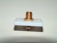
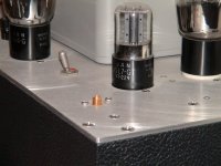
caps on the input RCA sockets
The idea is that the 10nF ceramic caps (My preferred value and type) which connect the ground side of the ISOLATED RCA socket to chassis locally cause the input cable shields (which are then at chassis potential as far as RF is concerned) to act like a physical extension of the box itself, extending the "Faraday Cage" and preventing RF from entering the box. If it can't get into the box it can't get into the circuitry and bolocks amp performance.
For similar reason I use filtered mains sockets (IEC Style) - always.
This just leaves speaker connections as input paths for RF to invade your box. I haven't sussed this one out yet.
Cheers,
Ian
a bit off topic..
I agree with never connect RCA ground to chasis. All the chasis noise and earth noise gets into the signal. Using the 10ohm//100nF seems to be the best trick.
However, I want to know if I have multiple sockets for output, how should I connect the earth wire? Should star grounding be used or connect the RCA earth in parallel? thanks
- Status
- This old topic is closed. If you want to reopen this topic, contact a moderator using the "Report Post" button.
- Home
- Amplifiers
- Tubes / Valves
- Question about using RCA jacks.