I'm beggining a new project, my own version of Thorsen Loesch Toccata Tube Phono Preamp. There is two versions of this preamp, the first version and the Mrk II.
They can be see at:
http://www.vt52.com/diy/diypage/loesch/toccata.html and
http://www.fortunecity.com/rivendell/xentar/1179/projects/toccata/Toccata.html
I will use the Mk II HV and heater supplies as first supply section.
Then I'll use HV shunt regulator for the preamp HV supplies in dual mono configuration. The heater power supply will feed separate tube heater current regulators. It seems that heater current supply sound better when using DC, a must for a phono preamp with high gain.
The preamp section is from the Toccata first version because the ECC88 is easier to source that the tubes used into the MK II.
I'm keeping the last preamp section to be able to drive more easily the interconnect and the following preamp, or I may use this last section to provide a High/Low gain switch.
My preamp schematic with notes and voltages readings is here:
Attachments
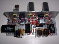
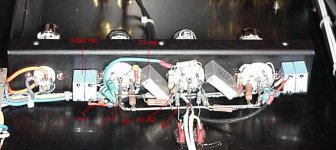
I already aseembled point-by-point the two channels. Each preamp is build on a aluminium L-channel, the 3 stages side by side. The input is at one end, the output at the other end to try to prevent feedback and oscillation. The image is showing that the assembly is quite compact. The signal connections are very shorts. In fact most connections are done only by the parts legs. A metal plate will mount on the top of the preamp L-assy (not shown) and will add some isolation and protection.
I tested the first channel and it is working perfectly. I indicated the differents voltage points on the schematic.
The RIAA curve is rather close, here the results:
RIAA Curve (Actual)
Hz Vout (dB)Theoric
20 +18.7 +19.6
50 +17.0 +17.0
100 +13.4 +13.1
200 +8.5 +8.2
500 +3.0 +2.6
1K 0 (Ref) 0
2K -2.6 -2.7
5K -7.9 -8.1
10K -10.4 -13.6
20K -20.0 -19.4
Attachments
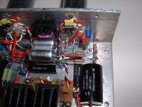
As I said, I'm using P-t-P assembly. Circuit junctions are connected to insulated standoffs. The HTR current regulators are using small PCB. I'm also using rather good quality parts: PRP (RIAA & Coupling), Vishay RN60D and Mills resistors, Solen Film (Supply), NOS Vitamin-Q in oil (Coupling) and Rohm Polystyrene (RIAA) caps, gold plated ceramic tube sockets and NOS Amperex ECC88 tubes.
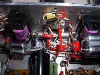
Here a close up of the first stage V1
Here a close up of the first stage V1
Attachments
The gain for the first section can be adjusted using resistors. The base gain is 4dB. I didn't try the others yet.
The preamp is using a split passive RIAA correction. The second stage V2 has 30dB of gain at 1Khz.
As you probably noted, this preamp is using for the last two stages a battery DC bias. I'm using 3V Lithium small batteries that should last years. They can be easily replace by unsoldering only one resistor in front of the battery socket.
Attachments
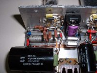
The last stage can be use as a normal preamp stage. I keep it for know. It has a gain of 28dB and can drive a load of up to 1.2K with a large voltage swing.
This assembly also keep all the parts away from the heat of the tubes, in particular the lithium batteries. All the resistors stay warm to the touch. By suppling the heater regulators with 10V, they also stay warm even with these small heatsinks.
I may need to reduce this last stage ouput to use it with a normal solid state preamp. I'll see...
I was forgetting, these images are for one channel only. Both channel are assembled in a mirror image fashion.
Attachments

New form of construction - "angle iron"?? ")
Looks clean... wonder what your hum floor ends up looking like?
I was able to dispense with the batt bias in a similar design... tube ran a little hotter, but not so hot that it mattered, and I got rid of the issue that the batt bias brings...
Is the ECC88 = 6DJ8?? I get the Euro numbers confused easily...
If so, I'd opt for some other tube myself... as I feel they sound a bit hardish and strident. Others my not agree, ymmv.
_-_-bear
In fact, I find it not that ugly. It is rather beautifull in an industrial kind of way. Anyway, beauty is a very personnal matter I was inspired by the Audio Experience Concerto Phono preamp for this assembly technic
I used this setup because it is rather easy to modify. I may try some other parts type, in particular the coupling caps.
I'm testing the preamp with a lab power supply and a signal generator for now. Then I'll build the normal power supply. I'm planning to use this preamp at the low gain setting with a step-up transformer.
If the noise floor is too high, I will try some other assembly, possibly a nice PCB with ground plane. This is also one reason why I try not to cut the parts legs too much. I can then re-use them in some other layout.
I cannot comment on the sound since I want to try it with the real supply. Thorsen had some good comments. I will see.
Any more comment on the battery bias? How did you modified your circuit to remove the battery, any schematic?
Here an example of the Concerto preamp
Thanks...
I was inspired by the Audio Experience Concerto Phono preamp for this assembly technicI used this setup because it is rather easy to modify. I may try some other parts type, in particular the coupling caps.
I'm testing the preamp with a lab power supply and a signal generator for now. Then I'll build the normal power supply. I'm planning to use this preamp at the low gain setting with a step-up transformer.
If the noise floor is too high, I will try some other assembly, possibly a nice PCB with ground plane. This is also one reason why I try not to cut the parts legs too much. I can then re-use them in some other layout.
I cannot comment on the sound since I want to try it with the real supply. Thorsen had some good comments. I will see.
Any more comment on the battery bias? How did you modified your circuit to remove the battery, any schematic?
Here an example of the Concerto preamp
Thanks...
Attachments
Algar_emi said:The RIAA curve is rather close, here the results:
RIAA Curve (Actual)
Hz Vout (dB)Theoric
20 +18.7 +19.6
50 +17.0 +17.0
100 +13.4 +13.1
200 +8.5 +8.2
500 +3.0 +2.6
1K 0 (Ref) 0
2K -2.6 -2.7
5K -7.9 -8.1
10K -10.4 -13.6
20K -20.0 -19.4
According to your figures, you have a large error at 10kHz. This may be because by changing the input stage, the RIAA network is no longer being driven by the source resistance the designer intended.
Attachments
EC8010 said:
According to your figures, you have a large error at 10kHz. This may be because by changing the input stage, the RIAA network is no longer being driven by the source resistance the designer intended.
The values used are the same as those in the published Thorsten version, so this is apparently exactly what the designer intended. Interestingly, Thorsten criticized his earlier pre as sounding too dark and closed in. With a nice 3dB peak at 10kHz, he seems to have dispensed with that issue.
Measuring the RIAA was not easy because my generator and supplies setup for the moment creating a lot of noise with all these flying wires.
I'm using a signal generator 50 ohms output and I measure using a HP334A distorsion analyser used as a relative dB meter, reference set at 1kHZ, 0dB.
I didn't change any parts values or configuration of the circuit. So far, I expect the circuit to works correctly unless there is layout or measurment error issues.
Also it seems that I have a ground problem issue between my signal generator and distorsion analyzer. The preamp section was also not as completed as on the photo. Some parts, like the batteries were connected using long wires. These batteries are used with very high value resistances and just touching them was creating problems.
I'll try again this weekend with the completed circuit.
SY said:Interestingly, Thorsten criticized his earlier pre as sounding too dark and closed in. With a nice 3dB peak at 10kHz, he seems to have dispensed with that issue.
Very interesting. I thought when you design a RIAA preamp, you should follow closely the RIAA curve. Sometimes I can get close to 0.2dB error from 10Hz to 30kHz, with real components. But maybe high end audio isn't about this

I'd agree that it is best to get as close as possible to the RIAA curve, at least within the ~20Hz-20kHz range... there are some thoughts about rolling off the extreme low end, and the same on the top...
Whatever Thorsten ended up doing with a peak at 3kHz., I suspect he was correcting a problem that was elsewhere, or in his ears/system...
Having done a number of very high quality tube based RIAA preamps, my experience is that small deviations in the curve screws up the area around 1khz., which in turn greatly effects the overall sound presentation! Getting the curve really right seems to be the only way to make it sound really right... at least that has been my experience.
My other finding is that one needs to accurately measure, and not trust any predermined circuit's values.
_-_-bear
bear said:My other finding is that one needs to accurately measure, and not trust any predermined circuit's values.
_-_-bear
Right Bear. You can get close to the RIAA curve up to 0.01dB but if real components do have 10% tolerance...
If you correct the RIAA equalization, this phono amp looks pretty promising.
Someone mentioned the batteries: To eliminate the batteries, it ought to be possible to tap the AC from the heater secondary to create a raw negative voltage supply using a diode or two and a couple of caps. Then use a series R with a shunt voltage regulator (perhaps a pair of those cheap red LEDs) to create a -3.4 volt supply. Since no real current is drawn by the grids, you could add several stages of long-time-constant RC filtering following the LEDs to remove every last morsel of noise.
A nit I noticed: the output ground reference resistor, R32 at 10K, could be made larger (maybe 100K) at the expense of a longer power-on transient, to lighten the load on the plates of V3A and V3B. Maybe this will be a pot – if so, never mind.
Thought I should mention that I got a strange email that is/was proported to be from Thorsten - but did not have his email address or name on the header... (which is odd since I have corresponded with him in the past...)
But anyhow, I personally have no knowledge of the response of any of his circuits, including this one. I am only going on what has been reported here in this thread. Then I added my comments based upon the content of this thread.
I hope that clarifies... for everyone.
And, if Thorsten is reading this thread, I hope he will simply participate himself rather than use surrogates, IF that is what is going on here.
<scratches head>
_-_-bear
- Status
- This old topic is closed. If you want to reopen this topic, contact a moderator using the "Report Post" button.
- Home
- Amplifiers
- Tubes / Valves
- Toccata Phono Preamp