As an initial experiment for building a new linestage, I just breadboarded a parafeed linestage (6N6p, Jupiter 4.7uf coupling caps, solid state CCS, magnequest iron) and it sounds terrific. Really terrific. Surprisingly so.
As I understand it, the biggest benefit of parafeed over a traditional single feed transformer coupled amp is that it gets the big electrolytic cap out of the signal path, and indeed, the clarity of the amp I built is very good. But, not everyone is building parafeed amps, and in fact in the scheme if things they seem to be in the small minority of tube amps being made. So it seems there must be a drawback. Can anyone tell me what it is and what other topologies might do better?
As I understand it, the biggest benefit of parafeed over a traditional single feed transformer coupled amp is that it gets the big electrolytic cap out of the signal path, and indeed, the clarity of the amp I built is very good. But, not everyone is building parafeed amps, and in fact in the scheme if things they seem to be in the small minority of tube amps being made. So it seems there must be a drawback. Can anyone tell me what it is and what other topologies might do better?
Well perhaps it depends on the application.
The very popular and excellent bang for buck power amp designs by Doc Bottlehead and Paul Joppa use SE parallel feed topology for the express purpose of elimating the B+ current from the OT. The DC plate supply is decoupled from the OT via a larger value cap (3.3mf or so), which definitely is in the signal path, so quality is very important.
Indeed some of the extreme tweakoholic upgrades to these amps often include exotica caps and output iron that can cost more than the orginal complete kit.
The single minus of a parafeed is a power consumption by a CCS load, no more minuses, pluses only. Better sound bought for wasdte of power, everyoner can decide what is better for gim/her.
One capacitor is no way worse than a saturated core. And if CCS is very good no ripples come from a power source, and no voltage regulation is needed since a load current is highly constant.
Why everyone don't use CCS loaded triodes?
Because beliefs and fashions rule the world. And because it is easier just to solder a transformer with a magnetic gap to anode of a tube.
chrisb said:The DC plate supply is decoupled from the OT via a larger value cap (3.3mf or so), which definitely is in the signal path, so quality is very important.
Right, I understand that, but the point is that it is a 3.3uF (4.7 in my case) high quality cap instead of the 100-470uF electrolytic that usually bypasses the cathode bias resistor.
analog_sa said:While it may do miracles for bass and prat, it sounds quite a bit artificial.
That's interesting. I'll just have to listen more to see what I think. So far I am enjoying it very much and am planning to next try it out with some 01A's I have around.
Why everyone don't use CCS loaded triodes?
I am a big proponent of CCS loaded triodes. You will find one in all of my recent designs. However some tubes (the 12B4 comes to mind) just don't like a CCS load.
Wavebourn said:The single minus of a parafeed is a power consumption by a CCS load, no more minuses, pluses only. Better sound bought for wasdte of power, everyoner can decide what is better for gim/her.
One capacitor is no way worse than a saturated core. And if CCS is very good no ripples come from a power source, and no voltage regulation is needed since a load current is highly constant.
Why everyone don't use CCS loaded triodes?
Because beliefs and fashions rule the world. And because it is easier just to solder a transformer with a magnetic gap to anode of a tube.
My suspicion is that parafeed is liked because it makes it possible to use P-P iron in a single ended application. That's one reason.
Other reasons include: it sounds ******* fantastic on things like power amps driving horn tweeters; it is extremely minimalist; people (as you imply) can experiment all day long with caps and chokes and output iron without much theoretical background; and some people want "gorgeous beautific sound" and this seems to deliver it simply and easily.
There are all sorts of CCS approaches out there for toobes - whole bunches of sites with people doing that. I think, iirc, TubeCad has a whole series of articles analyzing different topologies using CCS...
The other things that stands out in my mind is that "everyone" doesn't do "anything the same" in audio - everyone seems to have their own mix and preferences...

_-_-bear
Because beliefs and fashions rule the world. And because it is easier just to solder a transformer with a magnetic gap to anode of a tube.
Or maybe nobody else is as smart as you.
The only other problem I can see with a shunt-feed amp is that with no DC present in the magnetic core of the OPT, there exists the problem of the magnetic field collapsing as the AC signal crosses zero and the resultant nonlinearities which are easily heard. However, in the end, it's just a matter of taste and some people prefer one sound over another. I just happen to like the sound of a single-ended triode with a very large and unfortunately expensive gapped OPT. And it's not because I am lazy or fashion-minded.
John
Right, I understand that, but the point is that it is a 3.3uF (4.7 in my case) high quality cap instead of the 100-470uF electrolytic that usually bypasses the cathode bias resistor.
The AC signal no longer passes through the last cap in the power supply.
However some tubes (the 12B4 comes to mind) just don't like a CCS load.
My findings are opposite. Depends where you run them.
pm
I had a CCS loaded 807 amp. I couldn't live with the inefficiency of using a 700V supply for just 5-6Watts of output. I eventually converted it to choke loaded, but unfortunately it just didn't sound as good.
Parafeed is great in low level applications where optomisation doesn't cost the earth. In power stages it has cost/benefit limitations.
Shoog
Parafeed is great in low level applications where optomisation doesn't cost the earth. In power stages it has cost/benefit limitations.
Shoog
My findings are opposite. Depends where you run them.
I suppose that is true in many situations. The distortion characteristics of one stage may, or may not play well with the other stages in the amp. In my 12B4 experiments, I was running it at about 20 mA, using the circuit published here in the early posts of the 12B4 line stage thread. I was using a variable power supply, so I tried several different B+ voltages. That experiment is still sitting on my breadboard, asking me to power it up again. Too many projects, not enough time.
I did build a CCS (6LW6 - hybrid) loaded, KT88 (triode wired) experiment last year. See this thread:
http://www.diyaudio.com/forums/showthread.php?s=&threadid=67437&highlight=
The basic circuit details are here:
http://www.tubelab.com/Active loaded SE output.htm
I drove the single channel amp with the driver output of one of my other amps (CCS loaded 5842) it sounded real good, all 3 watts of it. But this was a temporary (and highly unsafe) mess of clip leads thrown together during a period of hurricane induced boredom. I took it apart, and added yet another project to my list of things to look into.
tubelab.com said:
I did build a CCS (6LW6 - hybrid) loaded, KT88 (triode wired) experiment last year. See this thread:
[
Hi George,
In a cascode MOSFET CCS, the MOSFETs have characteristics similar to a pentode. Every hybrid CCS that I have seen has the tube triode-wired. Have you tried, or thought of trying, a pentode-wired tube in to top of a hybrid CCS?
Dave
The only other problem I can see with a shunt-feed amp is that with no DC present in the magnetic core of the OPT, there exists the problem of the magnetic field collapsing as the AC signal crosses zero and the resultant nonlinearities which are easily heard. However, in the end, it's just a matter of taste and some people prefer one sound over another. I just happen to like the sound of a single-ended triode with a very large and unfortunately expensive gapped OPT. And it's not because I am lazy or fashion-minded.
The parafeed xfmr ideally calls for pinstripping by and/or contruction with exotic core materials which wont be saturated at these conditions (as there is no DC present) to mitigate this.
Have you tried, or thought of trying, a pentode-wired tube in to top of a hybrid CCS?
I have not tried it yet. I tested several popular tubes for use in the hybrid CCS circuit. I was looking mainly at the dropout voltage required to keep the tube in CCS mode. This can vary from 50 volts to 200 volts with the tube wired for triode operation. Pentode operation would require the screen voltage to be held constant with respect to the cathode. A zener diode or VR tube could be used for this. In my application (the KT88 test amp) I did not have enough B+ voltage to allow this.
Pentode mode should allow for a higher dynamic resistance which should be important for low level stages. The additional voltage should be available in this case.
In an output stage (I assume, but have not yet measured) the dynamic resistance of the CCS should be an order of magnitude or more higher than the plate resistance of the output triode. The effect of improving the dynamic resistance (which is in parallel with the OPT for AC signals) should not be too important.
This sounds like another experiment to add to my list.
The CCS testing is here:
http://www.tubelab.com/CCS circuits.htm
tubelab.com said:
I saw that page and that was what led me to my question. It is a very nice piece of work.
Dave
Output transformers for Parafeed?
Happy New Year!
I am considering a parafeed build, but I am not clear on my options for output transformers.
- Single ended output transformer - I know they are not necessary, but are there concerns in using them in a parafeed setup? I ask because if I don't like the parafeed build I can repurpose them.
-push pull output transformer - I believe these can be used without issue. Any requirements to consider?
- autotransformer - not clear on these at all. No experience with them.
-toroid transformer - No experience with them either.
- parafeed specific transformers - better core material, but at what cost?
Like most I am looking for performance to the point of diminishing return. I don't have transformers that I can repurpose so I will be buying new. Since I am not sure of my options, I will start with a budget of $100 per OPT. So far, I have only built SE amps using Edcor SE output transformers.
Transformers to be 2.5K:8 and at least ~10watts.
Any help is appreciated.
thanks,
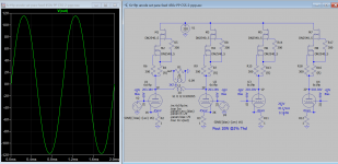
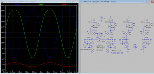
I'm considering this para-feed amp as my next project as I have a lot to 6c19p and 10W se OT. The efficiency is about 25% excluding heater power, Pout 10W ppp or 5W pp.
Parafeed-Amplifier Design
Parafeed-Amplifier Design
Attachments
Last edited:
- Status
- This old topic is closed. If you want to reopen this topic, contact a moderator using the "Report Post" button.
- Home
- Amplifiers
- Tubes / Valves
- Drawbacks of Parafeed?