zigzagflux said:Two parts versus six (minimum)?
I must be missing something.
Yes. Stability.
I developed a circuit about 15 years ago a bit like Wavebourns, but rather than trim a resistance to achieve the desired current limit on a per-case basis, I use a current sense resistor in the series pass leg to bias the base-emitter junction of an additional transistor that provides the current limiting.
I also run my regulated filaments a bit cool (5-10% below the nominal voltage rating) to extend tube life.
I also run my regulated filaments a bit cool (5-10% below the nominal voltage rating) to extend tube life.
thoriated said:I developed a circuit about 15 years ago a bit like Wavebourns, but rather than trim a resistance to achieve the desired current limit on a per-case basis, I use a current sense resistor in the series pass leg to bias the base-emitter junction of an additional transistor that provides the current limiting.
I also run my regulated filaments a bit cool (5-10% below the nominal voltage rating) to extend tube life.
Your approach is much better than mine for mass production. It eliminates one operation using extra parts that are cheaper than additional workplaces.
I have only done one valve based circuit and thoughtit was a no-brainer...
Lm317 running into parallel resistor of suitable resistance to get 365mA at 6.3V, one of the standard values came very close...
Then I simply conected it all ap switched it on (after some initial rough setting without a tube) and dailed in the voltage on with the trimpot. In retrospect I should probably have included the actual heater impendance in my calculations to find the resistor, but hey it works.
Wavebourn said:
Yes. Stability.
Valve Amplifiers, 3rd edition, Morgan Jones, p. 368:
In practice, the change of resistance with temperature is quite small, and heating power is more dependent on I-squared, so a current regulated supply is stable.
Exactly what I was trying to say. But again, which was not addressed, two parts ARE simpler than 6.
The theological discussion continues.........
:^)
anybody saw philips 12Axxx7 flashing during powering-up?
Yes I have several of those but no one with broken heater but some have low emission and/or are gassy due to old age, so whats your point?
The ones I have support my argument that heater failure is NOT the most common cause of tube failure and that therefore it is more or less a waste of time, money and effort to implement constant current or controlled heater supplies.
Regards Hans
tubetvr said:
...........................
The ones I have support my argument that heater failure is NOT the most common cause of tube failure and that therefore it is more or less a waste of time, money and effort to implement constant current or controlled heater supplies.
Regards Hans
that is exactly my point.
I like slow warm up,and I like to use CCS even for voltage oriented filaments ( adjusting exact voltage for hot filament) but all that just because I can-not because I must.......
I never saw broken filament in tube mounted in decent engineered circuit,even in most rudimentary one.
So, you take a filament transformer that can comfortably supply the heaters. You deal with EM, ES, filter the RF, and tie it to ground centrally By coincidence, you probably have a series resistance anyway for bringing the voltage down to where it should be.
Can anyone say there is anything not correct about this?
Can anyone say there is anything not correct about this?
hey wavebourne, thoriated, or zigzagflux,
1- Simple question: have you ever rigged up regulated supplies for 6.3V instead of 12.6? I assume you would have to switch D1 and D2 to 6V, but the rest looks like plug and play to me...
2- Even simpler question: is that a 2N412 or a 2N4124 on you schematic wavebourne.
3- Have you considered other solid state, such as 2N3055 and 2N2440?
4- Its a nice filiment supply, it looks surprisingly similar to one in a grant pre-amp circa 1986 that I recently rebuilt. Better regulation through diodes though. Is the red diode D2 supposed to be a LED?
Hi all
Just bringing this old thread to live as I have stumbled upon a CCS arrangement which I have not seen before, but seems to be very promising for the 'experimenters' between us. Also, it may be old news and not worth the hassle and 'forum polution' of a new thread.
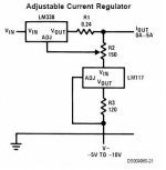
I copied it from National application notes for the LM138 and the LM338. The main advantage I see is that it allows for current setting over a vaste range with the use of a simple, small wattage, potentiometer. For voltages above 5V it does not require a negative supply, so most tubes could be fed by it.
I have just one question. What happens if the wiper loses contact? I imagine the LM338 CCS would just stop passing current, right?!
Thanks for the attention.
Erik
Just bringing this old thread to live as I have stumbled upon a CCS arrangement which I have not seen before, but seems to be very promising for the 'experimenters' between us. Also, it may be old news and not worth the hassle and 'forum polution' of a new thread.
I copied it from National application notes for the LM138 and the LM338. The main advantage I see is that it allows for current setting over a vaste range with the use of a simple, small wattage, potentiometer. For voltages above 5V it does not require a negative supply, so most tubes could be fed by it.
I have just one question. What happens if the wiper loses contact? I imagine the LM338 CCS would just stop passing current, right?!
Thanks for the attention.
Erik
Attachments
Holy cow. I've been wanting to see a circuit like this for a while. So simple. Very nice.
An open wiper looks to me to be oscillation-friendly, and possibly might drive full output current into your load. A 10K resistor from ADJ to the bottom side of the pot would be recommended. This should effectively turn the CCS off.
Very nice circuit.
An open wiper looks to me to be oscillation-friendly, and possibly might drive full output current into your load. A 10K resistor from ADJ to the bottom side of the pot would be recommended. This should effectively turn the CCS off.
Very nice circuit.
Wavebourn said:Or buid it such a way so it brings up the voltage slowly (R1,C2).

Thats a nice little reg. with inexpensive components - thanks for sharing it.
I have a silly question though - is D2 supposed to be an LED or a zener?
I have built it with a zener in that position and 17V from a voltage doubler off of 6.6VAC secondaries..
It seems to work fine (I don't own a scope..), but would an LED be better?
- Status
- This old topic is closed. If you want to reopen this topic, contact a moderator using the "Report Post" button.
- Home
- Amplifiers
- Tubes / Valves
- Is constant filament current better way to build amps?