Hi all,
today I found a nice wharfedale "rosedale" speaker and decide to recall to service my dusty Thorens PR15.
I notice then (having changed tubes), that I have problem with this strange filament circuit, the symptomes are:
- when music is played softly (~<1W) filaments (of preamp tubes) are way too hot !!! and there is distortion.
- when music is played loud (~>1W) filaments (of preamp tubes) are still hot but distortion is gone.
Here is a schematic (I'm sorry for the bad quality) that I have, but it don't seems to be anymore on internet (if anyone find a link or have it ...)
Any Ideas about the problem ?
Attachments
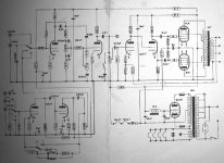
The filaments of the 12AX7's are being used as the source for the bias on the output tubes. I have seen this before (old Fishers I think). They are getting too hot because the output tubes (or something else) is drawing too much current.
I would bet on the coupling capacitors (the .1uF's on the grids of the 6L6's). Check the voltage on either side of the 330K grid resistors. If there is a significant difference the caps are leaking (or your meter has a low input resistance).
I would bet on the coupling capacitors (the .1uF's on the grids of the 6L6's). Check the voltage on either side of the 330K grid resistors. If there is a significant difference the caps are leaking (or your meter has a low input resistance).
Yup, what tubelab said. There's one other outside possibility. And that's excessive heater to cathode leakage in the rectifier tube. From the schematic, it looks as if they're running it with the other tubes. They should have used a seperate filament winding for that tube.
Victor
Victor
thx for your replies,
I think Tubelab pointed it too (the usual suspect...),
I had no time to look at it yesterday, but there is a least one error on the schematic: the rectifier is a GZ34.
from the schematic I think bias should be -(12.6+12.6+(39*0.15))
right ? (I am not sure to read correctly the resistor)
I think Tubelab pointed it too (the usual suspect...),
I had no time to look at it yesterday, but there is a least one error on the schematic: the rectifier is a GZ34.
from the schematic I think bias should be -(12.6+12.6+(39*0.15))
right ? (I am not sure to read correctly the resistor)
Ooops, my memory fools me ... schematic is right rectifier is a EZ81
I just had a look at the beast, and it seems that the series DC filament resistor (that is hard to read (29R ? 39R ?)) is a CTN or CTP !!! Is it original or replacement I don't know
I have to unsolder it and test it (maybe later today, with photos to come)
That could explain some of the facts, But what to do then ? (as I can't read the proper value on the schematic)
Any suggestion ?
DigitalJunkie said:
A bulb is a CCS for infrasonic frequencies.
bembel said:thx for your replies,
I think Tubelab pointed it too (the usual suspect...),
I had no time to look at it yesterday, but there is a least one error on the schematic: the rectifier is a GZ34.
from the schematic I think bias should be -(12.6+12.6+(39*0.15))
right ? (I am not sure to read correctly the resistor)
It should be 22-24V for 6L6 tubes. Don't torture the resistor, if it is bad you'd not see any filaments glowing.
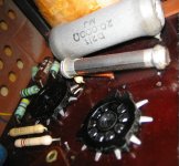
Indeed the resistor is a CTN/CTP (i allways miskate) here is a picture
the filament serie resistor is the closer one with no label.
> Its resistance is 30ohm cold (maybe 29R in the schematic)
> and higher when hot (about 45R with a lighter on for ten secionds)
Also I'm not really sure about current path ? doesthe B+ go back to the - side of HV (so it have to be 150mV !) ?
Attachments
If you follow the path for DC from the center tap of the power transformer, you see that all of the current drawn by the entire amplifier flows through the 39 ohm resistor and both 12AX7's. DC can't flow through the electrolytics, and only a small amount of current can flow through the 27K resistor. The only other path is through the filament circuit. Since the 12AX7's are designed for 150 mA, we must assume that the the design current is near 150 mA. The voltage would then be about 30 volts.
It is not too uncommon to put a resistor, light bulb, or zener diode in the return path of the transformer CT to develop a bias voltage. This allows the DC stability of cathode bias with the sound of fixed bias.
The excessive voltage can only come from excessive current. The excessive current is probably caused by sick capacitors.
Hi all,
Today I found time to work on the Thorens:
> Cap job, changed all electrolitics with derating (350 ->450)
> Changed coupling caps 100nF>80nF/1kV (what I had on hand)
> Changed a (broquen body) coupling cap (.02/150>.047/400) at the 1st 12AT7
then fired the amp, problem occur again.
B+ =192V C- = -62V both 6L6 grids @ - 500mv !!!
Ouch!!! It's still amazing to see that the amp still develops 5-10W of somewhat clean audio, the plates don't go cherry red either !??!
So I quickly picked the problem as a bad track leading C- to first bias resistor (27k).
After that the amp runs fine at:
B+ = 301V C- = ~grids = -22V
Any remarks about voltages ? (are you there tubelab ? ;-) )
I also plan to add a small cap // on the 2nd electrolytic. is 100nF a good value ? what technology is the more appropriate ?
Many thanks
Hallo,
sameone knowsif it is in class A1 or AB1. Lookking with the scope at the anode waveform I see acomplete sinus so I think is in class A1? Is this correct.
In the schema attached at the top of thos 3D there aren't the bias points for tubes. Someone measured these bias and can attac tothe schema or tothe 3D?
Thanks.
Hallo, I have a doubt with the scope I see the voltage but for knowing the operating class I need to know the current, Can someone hlep me to know the operating class of this ampli?
My ampli does not have the complete rear, can someone tell me the correct attachment for 8 Ohm loud (1 2 3 4 starting from the left and viewing from the rear)?
Thanks.
Bye
My ampli does not have the complete rear, can someone tell me the correct attachment for 8 Ohm loud (1 2 3 4 starting from the left and viewing from the rear)?
Thanks.
Bye
pr15 for sale
Just in case you wanted to make a stereo pair! what a nice pair that would be. : )
http://cgi.ebay.com/ws/eBayISAPI.dll?ViewItem&item=220213573946
Just in case you wanted to make a stereo pair! what a nice pair that would be. : )
http://cgi.ebay.com/ws/eBayISAPI.dll?ViewItem&item=220213573946
I'd like to piggyback on the question eta beta 60 asked.
The diagram on the connection of the speaker on the back of Thorens PR 15 is the following: for 4 ohm its the screws 1 and 4, with 1 and 2, and 3 and 4 respectively connected by metal jumpers. For 16 ohm its screws 1 and 4, with 2 and 3 only connected by a jumper. Just offhand I connect "+" to screw 1 and "-" to screw 4 without audible phase distortion. So - what is the connection for 8 ohm.
Another question is for French-speaking audiophiles (Pardonnez moi!) because the Thorens is a "Frenchman"") "Radio" must be tuner, Sortie - out for recording, Micro for microphone, Bande - ? and two mysterious PU, one of which is plugged by a wire coming from the amp itself, just like amp/pre connection on the integrated that could function as a preamp. Is it for phono?
"Radio" must be tuner, Sortie - out for recording, Micro for microphone, Bande - ? and two mysterious PU, one of which is plugged by a wire coming from the amp itself, just like amp/pre connection on the integrated that could function as a preamp. Is it for phono?
I read somewhere that a pre section on the Thorens could be by-passed so it may play as a pure monoblock with a separate preamp. Maybe the plugged PU jack is for that?
TIA.
The diagram on the connection of the speaker on the back of Thorens PR 15 is the following: for 4 ohm its the screws 1 and 4, with 1 and 2, and 3 and 4 respectively connected by metal jumpers. For 16 ohm its screws 1 and 4, with 2 and 3 only connected by a jumper. Just offhand I connect "+" to screw 1 and "-" to screw 4 without audible phase distortion. So - what is the connection for 8 ohm.
Another question is for French-speaking audiophiles (Pardonnez moi!) because the Thorens is a "Frenchman"
"Radio" must be tuner, Sortie - out for recording, Micro for microphone, Bande - ? and two mysterious PU, one of which is plugged by a wire coming from the amp itself, just like amp/pre connection on the integrated that could function as a preamp. Is it for phono?I read somewhere that a pre section on the Thorens could be by-passed so it may play as a pure monoblock with a separate preamp. Maybe the plugged PU jack is for that?
TIA.
jazzigor said:Another question is for French-speaking audiophiles (Pardonnez moi!) because the Thorens is a "Frenchman"
I read somewhere that a pre section on the Thorens could be by-passed so it may play as a pure monoblock with a separate preamp. Maybe the plugged PU jack is for that?
TIA.
Hi everybody, I was out for sometime due to work, but plan to be back soon.
jazzigor your guess are true for "sortie", "radio" & "mic". "Bande" means Tape and PU means "Pick-Up" the 60's term for Turn Table (I think that maybe those were not the same Z as nowadays cartridges, be careful).
Hope this helps.
à bientôt....
Bembel, thanks for the clarification. I haven't tried the PU jacks but plan to. For the past several days I've been listening to Thorenses and they sound very well thru an all-Thorens system (TD 125 II and Thorens-Restek little solid state preamp V2a) bar the speakers (Acousta Lowther DX2). I intend to tweak the amps a little because I think they differ in tubes (not paired), capacitors etc. So far the only question remains - how to connect 8-ohm speakers.
- Status
- This old topic is closed. If you want to reopen this topic, contact a moderator using the "Report Post" button.
- Home
- Amplifiers
- Tubes / Valves
- problem on thorens PR15 (strange filaments circuity)