Hello everybody,
I'm repairing this amp:
http://www.hi-figuide.com/apparecchi/amplificazione/finali/2000/melos/tm_90/index.html
Anybody has schematics?
It has been through years of service centers, because no one was able to fix it, so it has been donated to me.
It does blow the fuse on the B+, I tried with the series-lamp trick on the mains line and the lamp stays bright.
The big coke-cans 1400uF 200V caps seem to be right (but, strangely, I found one of them disconnected from the PCB. Strange.), and otherwise when removing the 1A fuse that's in series with the B+ (but not heaters, bias PSU, etc etc) the lamp flashes and then dims out.
Thanks anyone in advance.
Ok, I managed to remove the short (don't know what it was, probably a mechanical thing, not a shorted component).
One channel seems to bias correctly (I haven't tried to connect it to speakers), all the bias leds are working but the other channel makes strange crackling noise from the 6550s, and the bias leds go crazy. Also the cathode current jumps all the way in time with the crakcs, up to 200mA.
What could be this? I can't see any arcing inside the tube. Maybe the socket?
I removed the tubes and monitored the bias supply of the faulty channel: it has the voltage that jumps all the way from -20 to -70V, randomly. I think that's trimmer - related: I will replace all the bias trimmers.
Of course, of the many ways to connect a bias pot in an amp, they managed to use the worst way: this way if the trimmer opens (not rare: they oxidate) the grid of the 6550 goes to ground, 0Vgk
Very very strange input stage: I'm still trying to figure it out. Schematic would be much appreciated.
It has a 6AC10, that's 2 medium mu triodes plus an high mu triode all in a bottle, and a 6LU8, that is a beam power pentode and a triode in a bottle.
Ok I replaced all the trimpots but the problem is still there 
I'm looking at the 6550 grids of the left channel, without input signal there isn't just plain grid bias DC, but random waveforms, like sparks or arcing.
What could be? Coupling capacitors? But it's suspect that they fail both on the same channel...
I'm looking at the 6550 grids of the left channel, without input signal there isn't just plain grid bias DC, but random waveforms, like sparks or arcing.
What could be? Coupling capacitors? But it's suspect that they fail both on the same channel...
The coupling caps all test good on the meter! At least I checked for DC resistance, and it does show "charging up" effects, althougt not the same of some good other capacitor of the same value. They're suspect.
I will test by removing the bias supply (tubes unplugged) and see if there is still something on the grids.
(no schematic yet, sorry, I'm a bit busy in those days)
I will test by removing the bias supply (tubes unplugged) and see if there is still something on the grids.
(no schematic yet, sorry, I'm a bit busy in those days)
I disconnected the capacitors, and on 6550 grids there was nothing other than pure clean bias DC.
So I will replace the coupling caps.
However, their marking is strange to me: they're "customized" (branded Melos), 2.5uF and then 250V. Very very strange since this is a 550V B+ amp. Near the "250V" printing there is a little drawing, representing a sine wave. Does it mean that the 250V is an AC rating? If so, I guess they're good for 350VDC.
I can't find 2.2uF caps more than 100V rating, can I replace them with 1uF caps (Philips MKT, the orange ones) without upsetting too much the pole splitting of the amp? They don't look to be connected to a particulary low impedance (I measure 100k between grids and ground), so I guess 1uF is fine.
I will try, let's hope it does not oscillate or things like that
I replaced the coupling caps. But still the same problem, on the same channel. 
I can't believe they put 250V or so caps there: on the good channel, there is almost 380V continuous, and about 400V surge.
I guess I've damaged the caps I put in, but strangely the fault is in the same channel.
B+ is about 570V even at the driver tube, so I guess I need 630V capacitors.
I can't believe they put 250V or so caps there: on the good channel, there is almost 380V continuous, and about 400V surge.
I guess I've damaged the caps I put in, but strangely the fault is in the same channel.
B+ is about 570V even at the driver tube, so I guess I need 630V capacitors.
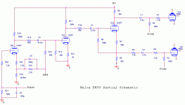
Had some spare time today, so I traced a rough and simple schematic of the input and driver stage of the amp.
Any idea on what can cause the trouble? I will replace the 2.5uF coupling caps (in the schematic, at the grids of the 6550) with 630V ones (althought 1uF ones), but I suspect there is still something not working.
I can exclude the plate and screen supply of the 6550s, because if I disconnect those 2.5uF caps, the 6550 bias perfectly without "sparks" or strange current jumps. I must add that the other channel does work and does sound good, so it can't be a plate supply problem (since it's shared). Screens are separately regulated for each channel with a separate supply. There's a shunt regulator made up of a solid state device (of unknown type: it's a T-03 with "1092 H8422" on the case), and they appear to work good.
Note that there's only the 6AC10 in the "signal" circuit: still wondering what does the 6LU8, maybe a B+ regulator for the input stages?
Here it is:
Edit: I forgot to mention that the tubes marked 12AT7 in the schematic are actually triodes of the 6AC10 triple triode.
Attachments
Just disconnect the coupling caps completely and see if it biases up OK. If not, you've got some socket work (probably) to do. If it does bias up OK, out with those old caps.
What's the value of the bias resistor? You probably don't need anything like 2u5, unless Melos really had a low frequency stability problem. On first glance, it would seem that the LF rolloff from the first stage coupling would be dominant and that a 1u/630V would work fine.
What's the value of the bias resistor? You probably don't need anything like 2u5, unless Melos really had a low frequency stability problem. On first glance, it would seem that the LF rolloff from the first stage coupling would be dominant and that a 1u/630V would work fine.

Hello all! Thank you very much for your reply.
Hello burnedfingers,
Instead, it isn't, I'm pretty sure, it does seem strange so I rechecked a couple of times. But there is an error in the schematic: the other side of the PP has the same 6550 grid arrangement of the other one (the one you notice as strange): the bias is directly on the 6550 grid, after the grid stopper resistor.
Some posts ago I already told of an experiment I made: I disconnected R4 and the 6550 biased fine.
Hello Stuart,
as I mentioned I disconnected R4 and that 6550 biased up fine. The bias resistor is 100k, so I guess I will be fine with 1uF caps.
All those consideration obviously lead me to believe that the old coupling caps (remember, 250V ones on a 550V B+, awesome they did resist fifteen years) are bad: but I replaced them with some 400V 1uF and the problem did persist. So now I re-replaced them with 630V 1uF (I found them ) and we'll see.
It isn't: I rechecked. It's strange, isn't it?
The big problem about this amp is that it needs the whole pcb dismounted from the chassis to remove a component (or even to look at the traces to draw a schematic), it needs about half an hour every time so now I replaced the caps with 630V ones, checked all the resistor you see in the schematic, all the other 2 coupling caps (the 0.22uF ones), they are all good. I don't doubt, if it was a more repair friendly amp, I could have done with it looong time ago.
burnedfingers said:R3 should be on the left of R4.
Change the (2) 2.5 uf coupling capacitors. I suspect that if you turn the bias off you will have DC voltage on the 6550 side of the cap indicating the cap is leaking.
Hello burnedfingers,
Instead, it isn't, I'm pretty sure, it does seem strange so I rechecked a couple of times. But there is an error in the schematic: the other side of the PP has the same 6550 grid arrangement of the other one (the one you notice as strange): the bias is directly on the 6550 grid, after the grid stopper resistor.
Some posts ago I already told of an experiment I made: I disconnected R4 and the 6550 biased fine.
SY said:Just disconnect the coupling caps completely and see if it biases up OK. If not, you've got some socket work (probably) to do. If it does bias up OK, out with those old caps.
What's the value of the bias resistor? You probably don't need anything like 2u5, unless Melos really had a low frequency stability problem. On first glance, it would seem that the LF rolloff from the first stage coupling would be dominant and that a 1u/630V would work fine.
Hello Stuart,
as I mentioned I disconnected R4 and that 6550 biased up fine. The bias resistor is 100k, so I guess I will be fine with 1uF caps.
All those consideration obviously lead me to believe that the old coupling caps (remember, 250V ones on a 550V B+, awesome they did resist fifteen years) are bad: but I replaced them with some 400V 1uF and the problem did persist. So now I re-replaced them with 630V 1uF (I found them
) and we'll see. burnedfingers said:Must be a mistake... R5 in front of C2
What is the B+?
It isn't: I rechecked. It's strange, isn't it?
The big problem about this amp is that it needs the whole pcb dismounted from the chassis to remove a component (or even to look at the traces to draw a schematic), it needs about half an hour every time
so now I replaced the caps with 630V ones, checked all the resistor you see in the schematic, all the other 2 coupling caps (the 0.22uF ones), they are all good. I don't doubt, if it was a more repair friendly amp, I could have done with it looong time ago.Hello burnedfinger,
I don't think it's possible, this is a PCB and it's very bad done, I haven't room for a grid resistor.
However I re-assembled it, tried and it appears to work. Still the left channel has those occasional jumps in current, but they seem to recover after a second or two. The other channel instead behaves good like it has always done. Strange.

- Status
- This old topic is closed. If you want to reopen this topic, contact a moderator using the "Report Post" button.
- Home
- Amplifiers
- Tubes / Valves
- Melos TM90 ST schematic?