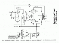
Hi Guys,
I'm interested in using this schematic but I don't follow how the gain stage/phase splitter is operating. As far as I can tell the gain stage/phase splitter does not have a DC reference on the cathodes only an AC reference. I see a 100 ohm resistor between the cathodes with a 100uF cap from one side of the resistor to ground. Is this a mistake in the drawing or do I not understand what I'm looking at (most likely)? Can anyone explain the operation of this stage? I would appreciate it much.
G
Attachments
THE WHOLE PICTURE....
Hi Gavin,
Yes,circuits like this can get a bit confusing....
Thing is you see grounding is taken,with B+ for the preamp to a separate chassis.
So as long as you don't see these two as a pair it won't make much sense.
The amp as shown get its signal straight into the phase splitter and that drives the output stage.
Cheers,
- Status
- This old topic is closed. If you want to reopen this topic, contact a moderator using the "Report Post" button.
- Home
- Amplifiers
- Tubes / Valves
- Need help with circuit operation. Please.
