I have a few nice e34 matched quads and wanted to build a single ended amp that had a bit of power. My speakers are sonus faber concerto's rated at 89db.
After discovering Andrea Ciuffoli's design on another thread, I decided that It would be a good choice. It would power my speakers nicely and has the added benefit of more or less doing away with the pre-amp stage.
here's the link to his amp:
http://www.audiodesignguide.com/my/el34_pse/el34pse.html
The output transformers aren't cheap by any means, but this didn't distract me. In fact quality transformers seem like a good idea in a single ended amp.
But then I looked at his power supply. His choice of a KBU6K looked a bit on the cheep side, and I immediately thought that a hexfred would be in order. And schotty diodes in the LT would also be a must.
But then I thought, what about valve rectification? Ok, the LL1669A power transformer may no longer be a good choice. I'm not sure if it has a tap. I have never done a valve rectification circuit, although I have repaired more than a few.
So a different (perhaps specially wound) power transformer may be necessary. And the current draw (including from the rectifier itself) would have to be considered.
I send Andrea an email, but he said his power supply would be adequate. I really like this amp on paper and think his site is fantastic!
I know he will read this, so I don't mean any disrespect, but what do others think? Is there a valve rectified circuit out there that would fit the bill?
Oh yeah, we have 230V mains here in switzerland... and this forum is really great!
There's probably no easy prefabricated solution. Duncan's PSUD is a great simulation program for power supplies; a little tinkering and you're done. I would strongly suggest the use of chokes and motor-run caps for best performance. The ps is very audible in se amps.
Good luck,
Simon
Good luck,
Simon
soulemerchant,
The lack of CT is not a big deal. A hybrid bridge with SS diodes forming the path to ground in combination with vacuum diodes works well. What you do have to worry about is the greater forward drop in vacuum diodes. TV damper diodes have small forward drops, for vacuum devices. A bridge made from a pair of UF4007 SS diodes and a pair of 6AU4GTA dampers just might be the ticket.
edit: fixed typo
Thanks Eli and Klimon
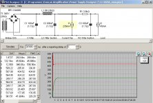
I downloaded psud2 - it is really great software.
It can't simulate a hybrid bridge, but I suppose I could just build it and measure the voltage after current draw from those el34's. I will just use the solid state bridge for now.
I estimated the current draw from 4 el34's at 234mA. This power supply also feeds half of a 12AX7 and half of a 5814.
I thought it might be nice to replace the 12AX7 and 5814 portion of the circuit. I don't like that cathode bypass cap on the 12AX7, and I need a phono stage as well.
I thought this phono and preamp stage designed by allen wright would be nice:
http://www.vacuumstate.com/schematics/fvp5a_s.gif
Basically I would replace the 12ax7 and 5814 portion (keeping the 0.33uf 450V coupling cap) with Allen's SEPH1x88 and SELT2 kits. The B+ for these designs call for 250V.
I'm pretty sure I can power this from the the same mains (see my attached picture). I estimated the current draw from 6 e88cc's at 45 mA per channel (half of 90mA). This brings the B+ for the End stage down a bit to about 425V in my spud2 simulation.
And I will need to source +20V for Allen's design so perhaps this isn't feesable withought a separate PSU. I'm still working this out...
Thanks once again for your help.
Attachments

Tweeker said:I think hybrid bridge can be simed by using 5AR4GRAETZ under tube rectifiers, should be close enough.
Didn't know that was there, nice. I just simmed both a ss bridge and a vacuum bridge and split the difference. Came very close to actual measured values.
Sheldon
Yeah, that's what I've done in the past (averaged, that is), I didn't know that 5AR4GRAETZ was there either.
But don't use a 5AR4 if you can avoid it. A hybrid bridge using TV dampers is a much better idea, as Eli says. Indeed, if you can spare the space for two separate diodes and you can provide enough heater current, TV dampers are always the best choice over other thermionic rectifiers. They're very rugged, tolerate a very high heater-cathode voltage and warm up quite slowly compared with other tubes - a really good slow start for your B+.
But don't use a 5AR4 if you can avoid it. A hybrid bridge using TV dampers is a much better idea, as Eli says. Indeed, if you can spare the space for two separate diodes and you can provide enough heater current, TV dampers are always the best choice over other thermionic rectifiers. They're very rugged, tolerate a very high heater-cathode voltage and warm up quite slowly compared with other tubes - a really good slow start for your B+.
- Status
- This old topic is closed. If you want to reopen this topic, contact a moderator using the "Report Post" button.
- Home
- Amplifiers
- Tubes / Valves
- PSE EL34 - valve rectification question