Hi DIYAUDIO Friends,
This is mine buffer with 6sn7. There are a CCS with BC547C transistors.
I'm thinking to put in on the output of the TDA1543. And the output on mine amplifier with 10x of gain and OPA627 for mine SENNHEISER HD580.

Is a GOOD idea put a CCS with transistors on mine buffer? I think the CCS with transistors is more linear than resistors. Is this good?
Thanks,
Felipe
This is mine buffer with 6sn7. There are a CCS with BC547C transistors.
I'm thinking to put in on the output of the TDA1543. And the output on mine amplifier with 10x of gain and OPA627 for mine SENNHEISER HD580.
Is a GOOD idea put a CCS with transistors on mine buffer? I think the CCS with transistors is more linear than resistors. Is this good?
Thanks,
Felipe
Attachments
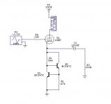
CCS loading of the cathode works very well. You'd probably want to run more current through the 6SN7- it's happy at 8-10mA. Understand that the effective load for the tube will be dominated by what it's driving- the CCS will just keep all the DC conditions stable.
You probably don't want to use a 100uF output cap!
You probably don't want to use a 100uF output cap!
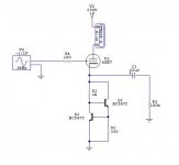
Is it a good idea put more current through the 6sn7GT?
If I put TWO Triodes on Parallel, CAN I drive a Sennheiser HD580?
I'm thinking to make only a buffer to drive mine head-amp, but if this buffer have low output impedance to drive a 300ohm headphone, it will be GOOD! VERY GOOD!
In the new attach, you can see the new version of this file.
=]
Thanks,
Felipe
Attachments
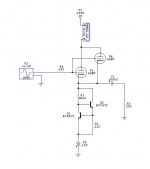
This is other simulation with two triodes on parallel, a 21mA across the tubes and negative voltage on the CCS.
With a 300R on the output, I saw 25mW ~ 30mW on the Transient Analysis of the Circuit Maker. This is very good for a Sennheiser HD580 or other 300R impedance Head-Phones.
Best Regards,
Felipe
With a 300R on the output, I saw 25mW ~ 30mW on the Transient Analysis of the Circuit Maker. This is very good for a Sennheiser HD580 or other 300R impedance Head-Phones.
Best Regards,
Felipe
Attachments
You're probably going to want to reference the ccs to a negative supply to assure you have enough voltage headroom real world. Either that or lift your grid well above ground potential with a resistor bias string and a coupling cap to your signal source. As implemented I doubt this thing can swing more than a couple of volts peak to peak and is highly assymetrical. (As designed the cathode cannot swing below ground whereas the grid can be driven quite negative relative to the cathode driving the tube to cutoff.)
I doubt it would drive a pair of headphones too well either due to lack of current and excessively high source impedance.
I doubt it would drive a pair of headphones too well either due to lack of current and excessively high source impedance.
I am posting a schematic by steve bench to show what Kevin is saying.
http://members.aol.com/sbench101/Crossover/xover.gif
R2 and R3 are biasing the grid to about 75V (half B+). That means that the cathode is at approximately 75V too...it can swing lots of voltage (almost from 0 to B+).
Erik
http://members.aol.com/sbench101/Crossover/xover.gif
R2 and R3 are biasing the grid to about 75V (half B+). That means that the cathode is at approximately 75V too...it can swing lots of voltage (almost from 0 to B+).
Erik
Erik,
Your image isn't opening in here.
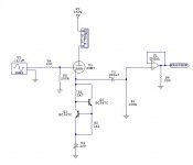
There are other idea to driver the HEADPHONE. I can make two outputs, in the frist, is the output on the tube.
The second output is the Headphone output. With a BUF634 buffer or other hi-grade op-amp for 1 gain.
This is my new schematic. The output op-amp is a BUF634. ( I think i can use a best schamatic in this part )
The power supply will have many CRCRCRCR stages.
Best Regards,
Felipe
Your image isn't opening in here.
There are other idea to driver the HEADPHONE. I can make two outputs, in the frist, is the output on the tube.
The second output is the Headphone output. With a BUF634 buffer or other hi-grade op-amp for 1 gain.
This is my new schematic. The output op-amp is a BUF634. ( I think i can use a best schamatic in this part )
The power supply will have many CRCRCRCR stages.
Best Regards,
Felipe
Attachments
Hmm... in this case the tube is there to add that nice 'tube sound'? If you do this I would use bipolar supply, that saves an input capacitor. And preferably just a resistor on the tail of the CCS, you know, those transistors take all the fun, I mean the tube sound, out.
Erik
for an example of a bipolar supply, with resistor to set current, look at
http://www.glass-ware.com/tubecircuits/6dB.gif
Erik
for an example of a bipolar supply, with resistor to set current, look at
http://www.glass-ware.com/tubecircuits/6dB.gif
Hmm...if you will be using a SS buf you could also use the 6SN7 as a simple grounded cathode . This will add some gain to the circuit (about 10X, bit more maybe) what may be not that bad. You said you will be using a TDA1543, which will put some 1,5V RMS out when fed with 5V. 1,5V RMS amplified by a factor of 10 is to much, but there is always a volume knob!
Erik
Erik
Here is an example, an interesting thread can be found here.
http://www.diyaudio.com/forums/showthread.php?s=&threadid=67433&highlight=
Attached is a 'modified' circuit from the above one...I took the cathode follower out...if you want it back, look at the above thread
Erik
http://www.diyaudio.com/forums/showthread.php?s=&threadid=67433&highlight=
Attached is a 'modified' circuit from the above one...I took the cathode follower out...if you want it back, look at the above thread
Erik
Attachments
ErikdeBest said:Hmm...if you will be using a SS buf you could also use the 6SN7 as a simple grounded cathode . This will add some gain to the circuit (about 10X, bit more maybe) what may be not that bad. You said you will be using a TDA1543, which will put some 1,5V RMS out when fed with 5V. 1,5V RMS amplified by a factor of 10 is to much, but there is always a volume knob!
Erik
Erik,
For the output of the DAC, i'm thinking to make this circuit with a 12AT7 or 6sn7.
But this is other project. The dac is one project, and this is other.
Is a good idea too, make a SRPP and a buffer for the headphones, in the same case.
Thanks,
Felipe
Attachments
- Status
- This old topic is closed. If you want to reopen this topic, contact a moderator using the "Report Post" button.
- Home
- Amplifiers
- Tubes / Valves
- 6sn7 Buffer