")
Whew!
That should satisfy you, CS! I have set the printer churning, since much of this that I had years ago went the way of al - er - books. My thanks to Giaime and Edl also.
Just an extra small point; I have a single graph illustrating that optimal conditions for fixed and cathode bias are not the same for minimum distortion; different load impedance as well as bias. Unfortunately I am not at home at present, and will only be able to post this by end of week. I have not studied the above data; it might be that you can work that out from these two sources.
Regards
ray_moth said:Johan, nice to read one of your posts again. Welcome back! How are you now?
Ray_Moth,
Sorry man, never replied. My injuries (broken ribs) have healed well and otherwise everybody (including my son where I still stay) are looking after me admirably.
The trauma of a lost spouse will be there forever, but life must go on. Taking part here is also a definite cure.
Thanks.
What is the anode current of the EL84 in your simulation?
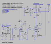
The cathode resistor of the EL84 is 152 Ohm. The dc-resistance of the primary is 156.4 Ohm. The supply voltage is 320 V.
The maximum anode dissipation of the EL84 is 12 Watt. So with about 300 V between cathode and anode, the maximum anode current is 40 mA.
Let's assume that the anode current in your simulation is 40 mA. The screen grid current will than be something like 6 mA. This would give a cathode voltage of 0.046 x 152 = 6.99 V. The voltage drop over the primary would be 0.046 x 156.4 = 7.19 V. So the voltage between cathode and anode is 320 - (6.99 + 7.19) = 305.82 V. The anode dissipation would than be 305.82 x 0.04 = 12.23 Watt, so already a bit over the limit.
But if you now look at the Ia/Va curves at Vg2 = 300 V in the datasheets for the EL84, than it becomes clear that at Va = 305.82 V and with a cathode voltage of only 6.99 V (so Vg1 = - 6.99 V) the anode current will be something like 85 mA instead of 40 mA.
The value of 152 Ohm of the cathode resistor is way too low. It can't produce the needed bias. The EL84 would not survive long in real life.
I'll stick to the more traditional design methods if you don't mind.
Last edited:
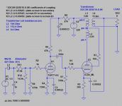
Okay I see what mistake I did. I started with another circuit which resembles very much the one I showed. Then I tried with resistor values of another circuit but forgot to adjust the supply voltage. Then I played with ultra-linear which changed the grid 2 voltage. Suddenly the tube dissipates 18 W. That is bad.
Sincere condolences to you, JohanThe trauma of a lost spouse will be there forever, but life must go on. Taking part here is also a definite cure.
 !
!Best regards!
So here is the circuit with the original bias values.
Why are there no voltages in the schematic?
A useful feature
Good question, but the answer is not as good. Years ago I used another Spice simulator, I think it was Microsim PSpice. That one had that useful feature that it displayed voltages and currents in the schematic drawing, and very easily. They could have been toggled on and off. But in this LTSpice I have been using, it seems that feature is not there. I did not find it. So, to visualize interesting currents and voltages I should first read them and then write them in the drawing as comments. In this case there are two vacuum tubes. Adding cathode voltage, anode voltage and current for both would mean six comments. Okay, it does not mean much extra work, but it is another task easily forgotten.
Why are there no voltages in the schematic?
Good question, but the answer is not as good. Years ago I used another Spice simulator, I think it was Microsim PSpice. That one had that useful feature that it displayed voltages and currents in the schematic drawing, and very easily. They could have been toggled on and off. But in this LTSpice I have been using, it seems that feature is not there. I did not find it. So, to visualize interesting currents and voltages I should first read them and then write them in the drawing as comments. In this case there are two vacuum tubes. Adding cathode voltage, anode voltage and current for both would mean six comments. Okay, it does not mean much extra work, but it is another task easily forgotten.
Re EL84 in ultra linear.
I find this quite good as one can select PP UL or SE and adjust parameters, I use it in conjunction with LTspice.
Loadline calculator for power stages with reactive load - Vacuum Tube Amplifiers - DIY
I find this quite good as one can select PP UL or SE and adjust parameters, I use it in conjunction with LTspice.
Loadline calculator for power stages with reactive load - Vacuum Tube Amplifiers - DIY
Good question, but the answer is not as good. Years ago I used another Spice simulator, I think it was Microsim PSpice. That one had that useful feature that it displayed voltages and currents in the schematic drawing, and very easily. They could have been toggled on and off. But in this LTSpice I have been using, it seems that feature is not there. I did not find it. So, to visualize interesting currents and voltages I should first read them and then write them in the drawing as comments. In this case there are two vacuum tubes. Adding cathode voltage, anode voltage and current for both would mean six comments. Okay, it does not mean much extra work, but it is another task easily forgotten.
Well, than just mention the cathode voltages of the 12AT7 and EL84. They don't have to be written in the schematic itself.
Good question, but the answer is not as good. Years ago I used another Spice simulator, I think it was Microsim PSpice. That one had that useful feature that it displayed voltages and currents in the schematic drawing, and very easily. They could have been toggled on and off. But in this LTSpice I have been using, it seems that feature is not there. I did not find it.
You can add a directive ".op" to your schematic.
1) Hit the "s" key to add a SPICE directive ".op" to your schematic.
2) Comment out the ".tran" and ".ac" directives. Run the simulation. No waveform will be displayed. You will see a window with voltages displayed. You can close that window.
3) Go back to the schematic and click on the nodes where you want voltages to be displayed.
4) Now you can reactivate the ".tran" or ".ac" directives as needed, and the voltages should display in the schematic at the nodes you selected in step 3.
I hope that helps.
--
- Home
- Amplifiers
- Tubes / Valves
- EL84 in ultra-linear mode