here's the schematic:
hopefully i'll get to building soon.
edit: i should cite this site ( http://www2.famille.ne.jp/~teddy/pre/pre3b.htm ) as a source, and the folks at diytube for some excellent insight, as usual.
An externally hosted image should be here but it was not working when we last tested it.
hopefully i'll get to building soon.
edit: i should cite this site ( http://www2.famille.ne.jp/~teddy/pre/pre3b.htm ) as a source, and the folks at diytube for some excellent insight, as usual.
It's interesting to do some simulations for the power supply. A few minutes with PSUD will convince you that at these low currents, three cascaded RC sections will have two or three orders of magnitude lower ripple and noise. The Rs are necessarily large values because of the need to drop voltage and that makes ripple currents low. For fun, start with an RC input and two more RC sections with about 3k and 100uF in each section. I like to put small resistors (a few ohms) in series with the filter caps to swamp out any nonideality that they have; in PSUD, you can do that directly in the cap specification. Anyway, that will get you down to a couple of microvolts.
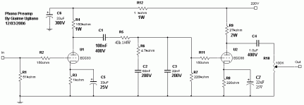
edit: why is that 3k resistor 10W?
edit: why is that 3k resistor 10W?
OK, first off, this is an OK schematic right? It's getting a lot of flak from different people, mostly in that the output Z is high (I don't know how to work Pspice so I haven't simmed it), that 12AX7's are bad, that feedback is bad, etc. The guy who built it really seemed to love it, which caught my fancy.
I'm not sure, I just figured 10W was safe. 280V * .003A = .84W so 2W would probably be fine. Thanks for pointing that out")
I also hear I should parallel a 20K resistor to the first 22uF cap in order to get a good current draw?
guy who built it = here at
http://www.diytube.com/phpBB2/viewtopic.php?p=5379#5379
SY said:why is that 3k resistor 10W?
I'm not sure, I just figured 10W was safe. 280V * .003A = .84W so 2W would probably be fine. Thanks for pointing that out
I also hear I should parallel a 20K resistor to the first 22uF cap in order to get a good current draw?
guy who built it = here at
http://www.diytube.com/phpBB2/viewtopic.php?p=5379#5379
The resistor is not dropping 280V, it's dropping about 10V. 3mA x 3k, more or less.
The preamp circuit itself... well..... errrrrrr.......
Doing something right in the Dynaco format is a very hard job. And that's the reason it hasn't been done after 5 decades and millions of experimenter hours.
The preamp circuit itself... well..... errrrrrr.......
Doing something right in the Dynaco format is a very hard job. And that's the reason it hasn't been done after 5 decades and millions of experimenter hours.
SY said:The resistor is not dropping 280V, it's dropping about 10V. 3mA x 3k, more or less.
The preamp circuit itself... well..... errrrrrr.......
Doing something right in the Dynaco format is a very hard job. And that's the reason it hasn't been done after 5 decades and millions of experimenter hours.
What do you mean, the "dynaco format"? Is that the whole idea of building up gain, then using the feedback to cut out the EQ? I'm shopping for a better schematic, so don't feel bad about not pulling any punches
Two 12AX7 in cascade, no buffering of the output or the drive of the feedback loop. There are a couple of variations here, mostly detrimental to performance.
The problem is that an RIAA stage with low noise, accurate equalization, low distortion, and good overload characteristics is hard to do. Morgan Jones's designs in his book seem excellent. So do Allen Wright's in "The Preamp Cookbook." I think he publishes some of these on his website, www.vacuumstate.com . You'll notice cascodes, current sources, complex buffers, and active regulation. Like I said, hard.
edit:
http://www.vacuumstate.com/various/SP-15_Article.pdf
http://www.vacuumstate.com/schematics.htm
The preamp circuit itself... well..... errrrrrr.......
SY,
If you have a suggestion....
Granted the supply can use some tweaking and the circuit might not be the greatest but then again I really haven't seen anything great pop up here recently.
Its about in line with the average piece arriving from Hong Kong being marketed at the $250 price figure. It would be an inexpensive piece to try and maybe something that would lend itself to some cheap tricks. Just MHO.
Being phono preamp poor I personally would jump at about anything..... I have managed to purchase two turntables and have a stack of records but no RIAA preamp.
If you have a suggestion....
I'd look at Allen Wright's FVP or Morgan Jones's Practical Preamplifier. They're reasonably simple, use reasonably easy-to-get parts, and are well-engineered. In the case of Jones's design, it is explained in enough detail that you can make your own adaptions or modifications with confidence.
I'll be publishing my own design soon, but it won't be simple or inexpensive, and it uses exotic tubes. And input transformers (oh, the horrror, the horror!).
OK, cool. I'll try browsing around, but you don't happen to have a couple quick links, do you? And how does the Seduction stack up against these circuits? I'm looking for simple, and high-quality, but would rather give up simplicity for a bit more o' the good soundsSY said:
I'd look at Allen Wright's FVP or Morgan Jones's Practical Preamplifier. They're reasonably simple, use reasonably easy-to-get parts, and are well-engineered. In the case of Jones's design, it is explained in enough detail that you can make your own adaptions or modifications with confidence.
edit: i'm guessing that morgan jones' design is in one of his books, maybe "valve amplifiers"? i think i got an idea for santa to help me out with :3I'd love to look at it, just for kicksSY said:
I'll be publishing my own design soon, but it won't be simple or inexpensive, and it uses exotic tubes. And input transformers (oh, the horrror, the horror!).


anyway, here's the schematic again because i think imageshack dropped it:
http://www.omgcomix.com/soren/riaa_schem.jpg
http://www.omgcomix.com/soren/riaa_schem.jpg
FVP can be used with MMs. I didn't look at what Allen has at his site, but the schematic in his book indicates that with a 47k input resistor and a 100R resistor in the source of the input FET, the gain and loading are optimized for MM.
Yes, the Practical Preamplifier is in Valve Amplifiers 3.
Yes, the Practical Preamplifier is in Valve Amplifiers 3.
sorenj07 said:It's getting a lot of flak from different people, mostly in that the output Z is high (I don't know how to work Pspice so I haven't simmed it), that 12AX7's are bad, that feedback is bad, etc.
Again I seem to arrive late at this topic. Still .......
Sorenj07,
First, let us get a few things v-e-r-y right here. The output impedance will be about 1,1K at 1 KHz, 12 K at low frequencies. I do not think that is unduly high.
Secondly, I have seen some inappropriate applications for the 12AX7 in power amplifier input stages, but nobody complains about that. For this application there is nothing wrong with it. It is a low noise low microphony triode.
Thirdly (and something I am getting a bit irritated with - not with members posting here, though), is this feedback-is-bad syndrome. It is only bad in the wrong application in mediocre circuits to begin with. Mostly it is an urban legend perpetuated. Let those who claim this give their technical reasons.
Giaime, I think the cap you are missing is perhaps h.f. attenuation for the RIAA characteristic over the 220K feedback resistor? This is taken care of in the 47K-1N5 network at the input. I prefer the network over the feedback characteristic, but it would need a small series resistor as a supersonic roll-off or a 10 pF cap over the 2nd triode's a-g1 for stability reasons. In the passive application as here the - 3dB point might depend slightly on the phono cartridge's impedance at h.f.
I use this circuit exclusively, merely because the feedback decreases what distortion might occur at headroom signals. But my main reason is because by shaping the coupling time constants instead of just making them large as here, one can also get a very handy 12 dB/octave cut below say 30 Hz. So your very expensive turntable is rumble free? You could get the same rumble-free performance from something for hundreds of $ less by including a rumble filter at no extra cost. Why not? Also it partly safe-guards your expensive loudspeaker from the odd stylus bang.
Unfortunately, Sorenj07, I cannot post my similar circuit just now because I am not at home. I will be able to in a week or so. If you are still interested then, my pleasure. In the meantime, I would say carry on. (The comments you already got regarding the power supply filtering apply.)
One last remark - I have not analysed your dc heater power supply, so again my comment would not be of immediate value, but one must be careful of a too raw dc heater supply. Dc can appear very pious, but one must be careful of proper filtering otherwise the charging spikes can create more noise than would a well laid out ac supply. I have generally not found an advantage (strange as it might seem) unless one uses some 15VAC input with proper filtering (large caps, fairly high series resistor) and uses the heater as a series 12V load. A spikey dc is certainly worse than properly laid-out ac with earthing through a selected mid-point via a parallel some 200 ohm pot.
A lot said without being able to post firm alternatives; hoping to oblige soon.
Regards.
OK, cool. Unfortunately, due to the continued uncertainty of the quality, the guy I was going to build for has decided to spare himself the "trouble" of working through a schematic, and buy a Bellari VP129 at some point in the future. As he is mostly into vinyl, and I am mostly into CDs, there would be no practical reason to build one for myself. I'd still love to see the schematic though !
As he is mostly into vinyl, and I am mostly into CDs, there would be no practical reason to build one for myself. I'd still love to see the schematic though !- Status
- This old topic is closed. If you want to reopen this topic, contact a moderator using the "Report Post" button.
- Home
- Amplifiers
- Tubes / Valves
- My RIAA Phono Stage Project