After looking at a variety of phono stages here and around the net, I decided to give this one a shot - at least as an idea. The basic schematic is this one from Steve Bench's site: http://members.aol.com/sbench101/Preamps/RIAA5.gif
I picked it partly because I've done another of his amp designs and was pleased with it, and partly because it's a little more than a basic circuit and will stretch me some. I'll be using it with an MC cartridge, so will put a step-up trans on the front end. It's going into a DEQX that has an input impedence of 10K, so I added a "Broskie" follower with noise cancellation. I changed the resistors a bit on the second ECC88 to divide the PS voltage in half at the plate. I also added PS noise compensation on the cascode stage.
I picked it partly because I've done another of his amp designs and was pleased with it, and partly because it's a little more than a basic circuit and will stretch me some. I'll be using it with an MC cartridge, so will put a step-up trans on the front end. It's going into a DEQX that has an input impedence of 10K, so I added a "Broskie" follower with noise cancellation. I changed the resistors a bit on the second ECC88 to divide the PS voltage in half at the plate. I also added PS noise compensation on the cascode stage.
Attachments
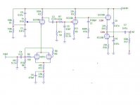
One problem I can see with the above, is that the 75us compensation will interfere with the PS noise cancellation at higher frequencies, even becoming additive at some point. So as an alternative I changed the circuit to an all in one pass type
RIAA network. Comments, criticisms highly encouraged.
The component values are not vetted, as I haven't included the effect of the coupling cap.
Sheldon
RIAA network. Comments, criticisms highly encouraged.
The component values are not vetted, as I haven't included the effect of the coupling cap.
Sheldon
Attachments
[
Thanks Brian,
Seems like that would work fine. Steve showed several different phono amps, including one with a 6DJ8 for the input. He claimed lower noise for the 6072. However, I don't think he did the direct comparison of the single 6DJ8 vs. the above schematic. The unbypassed part of the cathode resistor adds back some noise, so maybe it's a wash. He liked the sound of this one. Maybe some complementarity?
Sheldon
Brian Beck said:Sheldon,
Why not just use a single 6DJ8 in the lower part of the first stage? Fully bypass the cathode resistor for lowest noise.
Thanks Brian,
Seems like that would work fine. Steve showed several different phono amps, including one with a 6DJ8 for the input. He claimed lower noise for the 6072. However, I don't think he did the direct comparison of the single 6DJ8 vs. the above schematic. The unbypassed part of the cathode resistor adds back some noise, so maybe it's a wash. He liked the sound of this one. Maybe some complementarity?
Sheldon
Can't add much other than this is the phono stage I built, and it is very good. I built it on a blank PCB, using the copper as ground plane and dropping the grounding points wherever the component happened to be. If you're worried about noise from the cascode(low PSRR), search Broskie's site for noise cancellation in cascodes....I've never tried his techniques.
You will need a quiet PSU for the stock Bench design.
You will need a quiet PSU for the stock Bench design.
I certainly respect Steve Bench's opinion. He is one of the very few true innovators in tube audio. But it just seems to me that a 6DJ8 would perform better in the noise department if it is biased hotter than the 6072 sections. R2 would have to be reduced, and the RIAA values readjusted.
Other observations (right, wrong or half-baked):
Can you delete C4 and R10 altogether? C4 will slightly increase low frequency noise by isolating the MM resistance from the grid. I don’t see a reason for it other than very low frequency rumble reduction.
Put 10K safety resistors from both sides of pot R19 to its wiper, just in case the wiper goes open or gets dirty.
Move C3 after C1. Make it bigger than you would normally for best noise performance (“look through it” in both directions).
Can you bypass R5 (I didn’t calculate gain or overload margins here though), and then take the output right off the plate of the second stage? With an output resistance in the 2.5K neighborhood, it should drive most line stages if the cable is not very long. And then delete the whole CF with CCS.
There are probably several places to inject anti-phase PS noise. Look at the Marantz power amps for inspiration. They used capacitor dividers to re-inject anti-phase PS noise.
Just some spurious thoughts as I sit here in central Florida awaiting Tropical Depression Ernesto!
Another crazy idea I will probably regret posting:
Since R2 is already referenced to a presumably noisy B+ (the lower end sees a high resistance in the cascode which doesn’t ground it away), reference the signal voltages to B+, not to ground. Don’t fight B+ noise, join it!
Connect the bottom ends of C5 and C1 not to ground, but to B+. Bypass R5, not to ground, but to B+ also. Now the second stage will amplify only the difference voltage between grid and cathode, which are both referenced to B+, and B+ noise is largely ignored as common-mode. You’ll still end up with a ground-referenced output, so some noise re-injection/cancellation might be necessary, perhaps at the upper cascode grid, but the results might still have lower noise. Or, did anyone say OPT?
Sheldon said:Another possible approach to the issue of the 75us compensation interfering with noise cancellation is to compensate the cancellation network in like fashion. This feels like shakey ground to me. No?
Sheldon
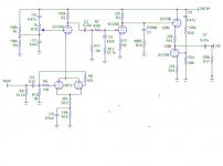
Thinking a bit more about this (Danger, Danger), it seems like it might work ok to just compensate the cancellation network too. The PS noise into triode before the buffer would roll of at 75us into the buffer. If I also roll off the noise injected at the buffer at 75us, it should cancel properly. Below, I added safety resistors before the buffer and adjusted the RIAA cap values.
I also switched the position of the coupling cap in the first RIAA section (so I can use a smaller coupling cap, ala Morgan Jones) and adjusted the RIAA values to account for the different impedences. Does this look reasonable?
edit: I had this sitting for a while and posted it before reading your last two posts Brian. I'll digest those and take another look at the design.
Sheldon
Attachments
SY,
Yes, that's always been my preference. But Sheldon seemed to have embarked on a noise cancellation approach (probably with Aikido in mind), and I was staying with his theme. Another cat skinning.
With a regulator, additional RC or LC filters and a good layout, PS noise can be conquered even for MC headamps.
I would think that any noise cancellation should be addressed at the cascode...vs the CF or whatever is used to drive 10K. I love the design, but if I were running a Denon 103 or other MC into it, I'd look at Alan Wright's Hybrid cascode as a solution, and drop the input transformers. In any case, a well thought out PSU is in order.
Brian Beck said:I certainly respect Steve Bench's opinion. He is one of the very few true innovators in tube audio. But it just seems to me that a 6DJ8 would perform better in the noise department if it is biased hotter than the 6072 sections. R2 would have to be reduced, and the RIAA values readjusted.
Other observations (right, wrong or half-baked):
Can you delete C4 and R10 altogether? C4 will slightly increase low frequency noise by isolating the MM resistance from the grid. I don’t see a reason for it other than very low frequency rumble reduction.
Put 10K safety resistors from both sides of pot R19 to its wiper, just in case the wiper goes open or gets dirty.
Move C3 after C1. Make it bigger than you would normally for best noise performance (“look through it” in both directions).
Can you bypass R5 (I didn’t calculate gain or overload margins here though), and then take the output right off the plate of the second stage? With an output resistance in the 2.5K neighborhood, it should drive most line stages if the cable is not very long. And then delete the whole CF with CCS.
There are probably several places to inject anti-phase PS noise. Look at the Marantz power amps for inspiration. They used capacitor dividers to re-inject anti-phase PS noise.
Just some spurious thoughts as I sit here in central Florida awaiting Tropical Depression Ernesto!
Thanks for all the suggestions Brian,
Since I was planning a step-up trannie on the input, yes C4 and R10 can go.
Yes, safety resistors on the pot, or fixed resistors once the noise has been trimmed.
If I did all in one pass, I could bypass R5. But I'd want someone to check my gain calcs. Remember, I'n going into a 10k impedence. If I want to split it and keep more to the original core, that impedence would make for a large cap on the 70us comp.
In my previous reply, I did move C3. Does this look about right in terms of position of things? Is 0.1u adequate (I have some nice teflons in this value)?
As far as injecting ps noise elswhere, don't encourage my tendancies to "improve" everything. I'm bad enough as is. It does look like I can counter the noise at just the two points, without capacitive dividers though.
Sheldon
Brian Beck said:Another crazy idea I will probably regret posting:
Since R2 is already referenced to a presumably noisy B+ (the lower end sees a high resistance in the cascode which doesn’t ground it away), reference the signal voltages to B+, not to ground. Don’t fight B+ noise, join it!
Connect the bottom ends of C5 and C1 not to ground, but to B+. Bypass R5, not to ground, but to B+ also. Now the second stage will amplify only the difference voltage between grid and cathode, which are both referenced to B+, and B+ noise is largely ignored as common-mode. You’ll still end up with a ground-referenced output, so some noise re-injection/cancellation might be necessary, perhaps at the upper cascode grid, but the results might still have lower noise. Or, did anyone say OPT?
Now that, l'm going to have to chew on for awhile. Seems like that would work too. Very much like the WE connection stuff I've seen here.
If I understand the application properly (got this one from Broskie too),R19 should allow good cancellation of ps noise on the plate of the cascode section. With the addition of C10 in the previous post, I should be able to get good cancellation of the noise on the plate of the second ECC88 triode. This is straight out of Broskie's Aikido book, except that I have 75us comp. cap on both sides of the follower. I'm a little more confident (perhaps confidance born of ignorance) that I can get this method sorted. I'm less sure on the capacitive divider approach.
OPT? Maybe, but I'm not sure yet how to put it to good use other than stepping up or down gain a bit. Given I'm going into 10k I'm not sure I could step up much.
Sheldon
SY said:Brian, here's crazy thought- how about just using a good, quiet supply? It's not like that's very difficult: a prereg and a cascade of RCs would do the trick.
He says with just a hint of irony. Fair enough, but remember, for me, this is intended also as a workout. So I wanted to paste together a few concepts and see if I could make something plausible. The cancellation ideas appeal to me just because, and also because the cancellation done in this way (very short loop) should allow cancellation of noise originating anywhere that gets into the B+ at the plate. Seems like that would have benefits beyond just quiescent noise levels. I'm paraphrasing JB here, but it makes some sense to me. I do plan a reasonably quiet supply (less than 100uV at least), but no reason I can't do both a very quiet supply and have the cancellation. The latter would be trivial to remove if it makes for problems.
Brian Beck said:SY,
Yes, that's always been my preference. But Sheldon seemed to have embarked on a noise cancellation approach (probably with Aikido in mind), and I was staying with his theme. Another cat skinning.
With a regulator, additional RC or LC filters and a good layout, PS noise can be conquered even for MC headamps.
What he said.
pedroskova said:I would think that any noise cancellation should be addressed at the cascode...vs the CF or whatever is used to drive 10K. I love the design, but if I were running a Denon 103 or other MC into it, I'd look at Alan Wright's Hybrid cascode as a solution, and drop the input transformers. In any case, a well thought out PSU is in order.
I have got cancellation both at the cascode and for the plate follower. They will both pick up PS noise. Why do you not prefer the input transformers? Yes, good PSU, but first this part.
Your comments are very helpful and much appreciated.
Sheldon
- Status
- This old topic is closed. If you want to reopen this topic, contact a moderator using the "Report Post" button.
- Home
- Amplifiers
- Tubes / Valves
- RIAA Phono Amp Design