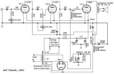
I liked my stereo 71-A amp so much, I thought I'd build a more deluxe version with two mono amps. Different driver scheme also with a pair of 01-A replacing the single 6F5.
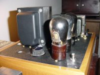
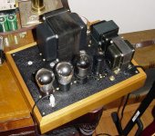
I'm using the smaller Welborne chassis, and the extra Hammond 1628SE output transformers, which I wouldn't normally recommend for this, because they weigh 11lbs! But they were just collecting dust here anyway.
I will probably end up useing a battery to bias the output tube as well, so ignore the silicon in the schematic...")
So, here it is:
I'm using the smaller Welborne chassis, and the extra Hammond 1628SE output transformers, which I wouldn't normally recommend for this, because they weigh 11lbs!
But they were just collecting dust here anyway.I will probably end up useing a battery to bias the output tube as well, so ignore the silicon in the schematic...
So, here it is:
Attachments
Joel
Your monoblock design looks interesting to say the least. I personally think that you will notice the difference in channel separation over your stereo version. What kind of power does it put out? What are you using for speakers? What kind of level can you get out of it? Geez, I'm asking alot of questions here.
Joe
Hi Joe,
This, like the stereo version, will put out 800mW per channel at clipping.
I'm using Altec two-way, horn + 15" woofer, speakers - called the Falmenco - which is an A-7 Voice of the Theatre system in a living-room friendly oak box. That's the same speaker used in Avery Fisher Hall here in NYC, and countless others. Almost 99dB efficiency.
They aren't terribly common anymore, but in the late 60's they were it for the well-heeled audiophile. I have old High Fidelity magazines that list the price as $385 each, in 1969! That was a lot of money.
Joel
Sounds like a nice amp to put together. I know for certain that the Altec Duplex speaker is the best point source speaker in existance to this day. The 60x40 horn does a great job. if my memory serves me correctly the efficiency of the different drivers were 101db@4ft per 1watt for the 602C driver, 103db for the 605 driver,101db for the 604E driver. I remember the 604 was in the Altec 858A Carmel.the 857A, and the 855A Malibu. I'll hunt at the shop today and see if I can pull the specs up on the Falmenco. It would be nice to share the information on these rare but beautiful drivers. If I look real hard at work today I'm sure we probably have one or two of these old gems still in the original boxes on the shelf.
Joe
Thanks for the extra info Joe. Sounds like you know more about them than I do. There isn't a lot of info on the net.
I certainly won't argue about the sound. I've had no desire to buy another set of speakers since I got these. The only possible exception would be a set of AR-2a's, to build up a real 60's system, just for fun.
I certainly won't argue about the sound. I've had no desire to buy another set of speakers since I got these. The only possible exception would be a set of AR-2a's, to build up a real 60's system, just for fun.
battery bias tip
Here's something for you kids to try at home:
Since I need a 40V battery if I want to battery bias the 71A, and you can't just go out and buy one - I made one last night. 13 lithium coin cells placed end to end, and wrapped up good with electrical tape, end up with a potential of just over 41V (close enough!). I used two ground lugs, one on each end, as the 'leads'. Final result is the same size as a AA batt, and cost $13. Should last a long time (2 years?).
So, there's no reason you couldn't add more cells to it for a 300B, or 45, etc. Unless someone can forsee a technical problem?
(note: Battery is then placed neg end to the bottom of the grid choke, pos end to ground).
Hey Joel,
Antique Electronic Supply sell 45 volt batteries. While I have a problem with them (I may just mail in orders with a check) you may not, and they are very good about getting your orders taken care of. I guess I am being stubborn.
http://www.tubesandmore.com
I am surprised you couldn't go down to Canal street and find a surplus place that may have them. Used to be a few "back in the day".
Or perhaps a local electronics supply place. On Parsons Blvd., by Union Turnpike, there is still Stuart Electronics (if you live in Queens) that may have them.
Otherwise your idea is cool! It is smaller, too, and would last longer. I may try it for my antique battery radios. I currently use 10 9-volts connected to each other by their connectors, leaving the two ends open and use a clipped in half 9 volt connector for the open ends. Works great... for a little while till they run down. Perhaps you could also use 5 9-volts to get 45 volts. Just use a resistor in line to drop the 5 volts (choose the right one for the best sound. Just kidding!!!! Smile!).
I got the idea from a fellow antique radio guy somewhere on the web. I can look it up for you if you are interested to see a pic of what he did.
Gabe
Hey Gabe,
Yeah, Canal St ain't what it used to be. Most of the places I've been in just give me blank stares. Leeds in Brooklyn is the sh*t though. Richard sells on eBay all the time and is a straight up guy.
The problem with using a resistor to drop some voltage on the grid is the same problem that I would have with my bias scheme as it is in the above schematic - more DC resistance in the grid circuit. The point of the choke was to lower it as far as possible, so I was adding at least 5-10k more with the pot trick, and to drop a whole 5 volts using just series resistance would take probably a meg or two (since there's no current draw in the grid circuit.... or there shouldn't be at least!). Thanks for the FYI though.
Peter,
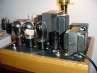
Well, I really just wanted to use the 01-A, and that necessitated using two of them because their gain is so low. They're a natural match to the 71A - same filament voltage/current, same basing - and they would have originally been used together in receivers. I was going for a 20's-30's retro look and design.
If you want to see my minimalist version of this, look up my other 71A posting. I used a single 6F5 per channel.
Fair enough. Actually, it's not so much transparency i worry about. All my tube creations use a separate tube rectified PS per stage. I simply refuse to accept that two stages could possibly share the same supply. Well, maybe a really good, possibly shunt regulator may replace the separate supplies but i still haven't had luck with one. All this contributes significantly to the weight and i'm not so young and strong any more
cheers
peter
cheers
peter
PSU+SHUNT REG
Hi Peter,
Neither do I.
What I do is use a tube shuntreg per stage in the amplifier bar the outputstage unless it's low power.
In a phonopreamp I would take that even further and use separate Xformers,rectifiers and shuntregs on per stage basis.
All this hardwired,stargrounded and on a dual mono basis.
The PSU gets a dedicated chassis as well.
It is my recipe for a realistic soundstage combined with very high resolution and bass you wouldn't believe till you heard it.
Cheers,
Hi Peter,
I simply refuse to accept that two stages could possibly share the same supply.
Neither do I.
What I do is use a tube shuntreg per stage in the amplifier bar the outputstage unless it's low power.
In a phonopreamp I would take that even further and use separate Xformers,rectifiers and shuntregs on per stage basis.
All this hardwired,stargrounded and on a dual mono basis.
The PSU gets a dedicated chassis as well.
It is my recipe for a realistic soundstage combined with very high resolution and bass you wouldn't believe till you heard it.
Cheers,
Frank
do the shunt-regs allow you to get rid of all chokes? i am still concerned 'bout my ageing back. Care to describe in general terms your regs topology and shunt tube type? I am just about to fully redo my phono and very keen on weight reduction, don't even ask me how many chokes are there currently (that's since i found a choke in each PS ground line greatly contributes to groovy bass)
peter
PSU REG
Hi Peter,
Well,this will make your aching back very happy.
For instance for a B+ of roughly 300V I often use a trioded EL86/6CW5 as a series element.
A ECC83/12AX7A as a dual stage error amp and in this example a OG3/85A2/5651 glowdischarge tube as a reference.
If you want the get rid of the chokes the "ripple killer"* circuit should do the trick as you can put some serious caps between its' output and the shunt reg.
Behind the regs (contrary to common belief that you can't) I still put some heavy caps behind the reg.
Never,ever saw the voltage sag,this is a rock stable PSU with exceptional PSURR.
For higher voltages you can use the OA2.
A more economical alternative for say 250V B+ could be built around the ECL85.
*RIPPLE KILLER
**
NOTE:I personally never built this circuit but from what i see it should work,it uses a 12AT7A/ECC81
Btw,did you use chokes in both B+ and ground rails?
Ciao,
- Status
- This old topic is closed. If you want to reopen this topic, contact a moderator using the "Report Post" button.
- Home
- Amplifiers
- Tubes / Valves
- a 71A monoblock