Hi Everyone,
I have a Velleman K4040 valve amp which I have had for a couple of years. The unit works fine most of the time BUT does have an unusual problem which has been present more or less from day one.
The amplifier tends to blow “lots” of EL34 output valves destroying the corresponding 10ohm bias resistor. To date, I have lost around “10” output valves. Some were new valves which did not last more than a few days. I’ve tried many different new valve types including KT-77’s etc and several NOS valves with the same result.
The time period between blown valves varies from several months to only a few days. I seem to loose more valves from the left channel than the right. The amplifier in between valve failures works and sounds great. Any ideas how I can eliminate the problem? Constantly replacing valves is becoming a very expensive exercise. HELP!
Cheers
George
This is bad. If I had a design that zapped my NOS then there's real trouble somewhere. What'about if one had a car which behaved like this ? A good design should have tubes that last years not months.
Perhaps we need to know what happens onset tube failure.....glowin' tubes, screen grid glowing inside, or loose bias connections. Does it seriously crackle when one fists the chassis ? I often do this test before I go on-stage. A well designed tube amp should take the physical rigours....tubes are pretty robust.
It isn't unknown for poor soldering on tube pins. check these.
richj
there are other issues, apparantly, some el34s do short occasionally, it may be screen grids, and it may also be bias.
the best el34s are jj, EH, and valve arts, also svets.
make sure the amp is run always with speaker connections, it shoudln't matter with no signal, but still valves/tx's don't like open circuits.
so cool the output stage down, I suspect this fella is a class AB, tho, and if that doesn't work, use 5881s, they are quite cheap direct from russia.
if that doesn't work, check for any shorts, and output tx's, its poss there may be a winding short, then get new ones, or throw it out.
I'm unfortunate enough to own a 4040 also even though its been used as a fancy door stop the last few years. I had the same problem with it eating EL34 tubes. It seems they really run them hot. Ironicly the only EL34s that seemed to last were also the worst sounding ones, the original Sovteks that came with it. I ended up converting it to run JJ KT88 tubes. All that involved was putting in higher wattage same value bias resistors and using 1" spacers on the sockets so they are now up in the holes in the chassis. Otherwise the KT88s won't physically fit because they have bigger bases that won't fit through the holes when the sockets are recessed. Never had a KT88 fail in it.
Dave
Dave
DAve...40mA plate quies that's a bit low for KT88's ? What 's the B+ on the Velleman 4040 ?
I've been using 60mA quies on Svet 88's at 530V without fuss.
JJ88's appear to run better but bias isn't quite same as Svet 88's- roughly 10V lower with JJ. THD is also up a notch.
richj
I've been using 60mA quies on Svet 88's at 530V without fuss.
JJ88's appear to run better but bias isn't quite same as Svet 88's- roughly 10V lower with JJ. THD is also up a notch.
richj
Its been a few years since I've messed with it but it was up near the top end of what a el34 could handle. The 40ma is the same as what the el34 runs at on a stock 4040. I know the 40ma is low and I was going to play around with that assuming the power supply in the 4040 was up to it but it sounds loads better than the el34s did in this unit and no more fried tubes..
Dave
Dave
Through the decades of tube amp design I've been far more performance impressed by running output stage in parallel pairs UL p-p and at quite low B+ i.e 270V or so. The tubes run at 80mA quies have a very long life and near "quasi'' class A performance.
parallel pairs Kt88 at 265V B+ UL will give a little over 30W poke but it sounds way louder when compared to my GEC 88-50 Watt. That runs at 500V and it doesn't sound so good in the mid-range.
The emphasis is then on the power supply.
I did buy a set of KT90's and completely dissapointed with'em. the anodes glow red at 60mA whereas JJ88's just sit black.
Some time ago I stirred up quite a fuss regarding the Velleman performance basically of using an ECC83 to drive KT88's. Perhaps this was a typeset error but I was latercinformed it was an 83. What !
There must be something radically wrong with the amp design if EL34's get gobbled up. These tubes in their hayday were the best class audio ouput tube produced.
richj
I am not entirely sure, but the driver tube has to do 2 things current wise...
charge the input cap of the output valve
and supply current to the grid if it starts to conduct, these 2 may be related.
so point 2 is largely irrelevant if you stick to class 1.
As to point 1, it will limit top end and slew rate, and again that may not be consequential, I have seen ecc83s driving 3 pairs of el34s, and even some faily hi cap triodes.
if paralleled, it will double current, the top end of the output tx may be more of a factor. ecc83s do give a gutsy sound that I quite like. guitar amps use them almost exclusively.
I am going to try driving a 300b with an 83, not done, but I will judge on the sound, it will raise eyebrows
just listen and see if you like it, a lot of the time, the theory doen'st sound good in practise.
Here it is:
An externally hosted image should be here but it was not working when we last tested it.
GeorgeK,
G'day from Adelaide - I'm running a similar amp, home built using Plitron Toroidal Output Tranny and Power Tranny with +485V on the EL34 and biased at 45mA, that is, I'm running them even harder than you are in the K4040. I've had similar tube failure problems from time to time. Most of the EL34s I've lost have been cheap Chinese and JJ's.
I changed the screen resistors on the EL34 to 1K 5W. Do this to your amp, R93, R94, R95 and R96 to 1K 5W. For Ultralinear Mode 180R is just not enough and you may even be getting parasitic oscillation. I originally had 150R screen resistors and DEFINITELY had a oscillation, I saw it on the oscilloscope). If the 5W you get from the local hobby shop won't fit then the 3W Vitreous Enamel Wirewound Welwyn you can order from Farnell will do the trick (Cat No 950-3692).
I finally settled on "Winged C" Svetlana EL34s - not only were these more reliable than the JJs BUT they also sounded better - unfortunately they also cost a fair bit more. So give Arthur a ring (Evatco) and see what he wants for 2 quads.
The problem may also be associated with the large Rg1 values on the EL34s and EL34 grid current - unfortunately fixing that is a larger problem. A better quality tube with less grid (Leakage) current would alleviate that problem to some degree which is why the Winged C Svets might be better. If anyone decides to tackle a fix for that, then check out 12DW7 to see if the "12AU7ish" side is correct to suit the PCB layout for the concertina splitter (12DW7 is like 1/2 a 12AX7 and 1/2 a 12AU7 in one envelope). If so, double the current in the concertina dropping the 47Ks to 22K and halve the 220K and 100K resistors and pots (Oh and double the coupling caps).
Hope this helps,
Cheers,
Ian
Im a bit suprised running a parallel ul o/p stage without snubbers with high gm tubes such as 34/6550, KT88 class with top flight ouput transformers. I use them especially when high capacitively loaded piezo uppers are used.
My immediate design instinct is to run a square wave through the amp at low sig level and see what the waveform quality is at 10Khz at the o/p tranny sec. I believe the amp uses pcb design, the layout is important for good output stage performance.
Ok my worst fears regarding the 83 but had this amp arrived on my bench I would butchered the phasesplitter and front end for something better....the aim is not to get excess slewing in preceeding stages before the output stage slew limits so it under performs with high distortion.
I'd always thought the 82 would be better than an 83 vis a vis in this application esp for driving a double power stage.
Rich,
I copied this from a previous post (and edited it) COZ its worth repeating.
The 12AX7 concertina splitter is going to be much better than you might expect (Could certainly be improved thou')
FOR A CONCERTINA SPLITTER:
For equal loads on Anode and cathode
Zout = RL.ra/RL(u+2)+ra
The ra term on the bottom line is insignificant compared to RL(u+2) term so drop it. Then the RL terms top and bottom lines cancel leaving
Zout approx = ra/u+2
At typical values of u (>=20) U+2 approx = u, so simplify again
Zout approx = ra/u = 1/gm
For a 12AX7 that means Zout approx 650 Ohms
If driving output stage directly The equal loads on Anode and Cathode will NOT be guaranteed if:
1) Output stage strays out of Class A (When a tube cuts off it has no gain so Miller capacitance will change, particularly with Triode Mode Output, less so with Ultralinear and less so again in Pentode Mode)
2) Output Stage strays into grid current.
If the Anode load drops significantly then:
Zout cathode = (RL+ra)/(u+2) x ra/RL ; ra/RL term insignigicant so
Zout cathode approx = (RL+ra)/u+2 ;at usual values of u
Zout cathode approx = RL/u + ra/u = RL/u + 1/gm
That is it increases by fixed amount of RL/u
If the cathode load drops sifgnificantly then:
Zout anode = RLxRL(u+1)+RL.ra / RL(u+2)+ra
RL squared (u+1) is much larger than RL.ra and RL(U+2) is much larger than ra so simplify expression to
Zout anode approx = RLxRL(u+1)/RL(u+2)
and at reasonable values of u
Zout anode approx = RL
Summary:
As the loads on Anode and cathode become unbalanced then
Zout anode increases from 1/gm toward RL
Zout cathode increase from 1/gm toward 1/gm +RL/u
Thats why its suggested that low u is better when driving other than Class A Output Stage.
For a 12AX7 that means:
Zout anode increases from about 650R toward 47K
Zout Cathode increases from about 650R toward 1.2K
You can see why a high current (low RL) and low u solution would be better in the unbalanced load condition.
This analysis is based on the Morgan Jones treatment in "Valve Amplifiers" 3rd Ed.
For the K4040 Amp I would be increasing the output tube idle current to at least 50mA to give more Class A Power before the CLass AB transistion for just this reason.
By snubbers I take it you mean zobel networks between Anode and Screen connections on the Output Tranny???
Cheers,
Ian

Ian, aes you are quite right. When I design around a concertina phase spl' I always use a buffer driver stage to drive o/p tubes. Williamson did it and so did the others. That takes care of the HF misbalance which the concertina has. My favourite is an ECL82 penny connected as triode in common cathode config and scrap the triode section. The load lines don't look ideal but all features, gain, noise perfom, thd, freq response and output Z are excellent.
As to the 4040, To drive parallel o/p stage with 415V B+ the driving voltage (g1) on each p-p stage grid would be around 35-40V that's too much for a ECC83 driver and without enough low Z. It strikes me that the output stage is actually controlling the phasesplitter !
C19,20,21,22 do seem very low in value.
I ought to post my design . It's in old microsoft designer so will have to manipulate it into another program.
:-more later
richj
Ian# Gingertube,
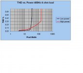
Circuit dia of 30/ 150 watt power amp. Power supply uses Switchmode /PFC not shown.
Graph of thd 400Hz performance.
I can recommend this amp although the 7199 is getting on the rare list
The circuit is simple but amps of this class there is alot of safety watchdogs and warm up procedures thrown in.
Generalised;
s/n -70dB down full o/p
no measurable switchmode interference.
richj
Attachments
- Status
- This old topic is closed. If you want to reopen this topic, contact a moderator using the "Report Post" button.
- Home
- Amplifiers
- Tubes / Valves
- Velleman K4040 is Always Blowing Output Tubes