is it vice-versa?
I have 2 transformers. One of the B+ and rectifier tube and another one amp tubes.
I will be using regulated DC supply for the amp tubes' heater(no discussion on ac vs dc please") ) and I'm thinking of using a "slow turn on" supply like the one describe in the LM117 datasheet.
) and I'm thinking of using a "slow turn on" supply like the one describe in the LM117 datasheet.
Furthermore, I am thinking (not definite yet) of using an NTC thermistor from Epcos:
============
33ohms
2.5A
Highest/lowest category temperature: -55°C to +170�C
Max. energy at 25�C: Pmax 3.1W
Resistance tolerance: ÄR/RN �20%
Nominal temperature: TN 25�C
Heat conductivity (air): äth approx. 17mW/K
Therm. cooling rate constant (air): ôC approx. 90s
Thermal capacity: Cth approx. 1.530mJ/K
==============
The thermistor will be place on the IEC socket. So this means both transformers are covered.
===================================
1. As the title says, I'm wondering if the amp tubes should already be hot when B+ is applied?
2. is the thermistor even required to achieve an over-all slow turn on? or the slow turn-on of the regulated dc supply be enough?
Thanks for the help
I have 2 transformers. One of the B+ and rectifier tube and another one amp tubes.
I will be using regulated DC supply for the amp tubes' heater(no discussion on ac vs dc please
) and I'm thinking of using a "slow turn on" supply like the one describe in the LM117 datasheet.Furthermore, I am thinking (not definite yet) of using an NTC thermistor from Epcos:
============
33ohms
2.5A
Highest/lowest category temperature: -55°C to +170�C
Max. energy at 25�C: Pmax 3.1W
Resistance tolerance: ÄR/RN �20%
Nominal temperature: TN 25�C
Heat conductivity (air): äth approx. 17mW/K
Therm. cooling rate constant (air): ôC approx. 90s
Thermal capacity: Cth approx. 1.530mJ/K
==============
The thermistor will be place on the IEC socket. So this means both transformers are covered.
===================================
1. As the title says, I'm wondering if the amp tubes should already be hot when B+ is applied?
2. is the thermistor even required to achieve an over-all slow turn on? or the slow turn-on of the regulated dc supply be enough?
Thanks for the help
==> If you can, refer to the book by Morgan Jones titled "Valve Amplifiers"; there is a section in the book that addresses the very question you ask.
I don't have the book in front of me, but if I remember correctly, he suggests something like this:
The heater should be powered to ~65% of full voltage before the B+ is applied. It is bad to turn on the B+ to the amp cold, and it is also bad to apply the B+ to the amp when the heaters are fully on.
rtarbell said:==> .....and it is also bad to apply the B+ to the amp when the heaters are fully on.
Never heard about this before...
Any sensible and REAL reason to do this?
Have been doing EXACTLY the opposite for about 8 years to the same 6550C Svetlana quartet set of tubes and 1 month ago checked the emission on them: 82% (and just the same emission for a BRAND NEW 6550 Svetlana I have as a spare)
And none other problems whatsoever.
[ ]
Ricardo
Hi Ricardo, Jarthel,
You normally want the heaters to be running and up to temperature before applying B+. This is to limit HV surge on the unloaded power supply and also to prevent "cathode stripping". At lower values of B+, there isn't too much harm in applying B+ to the plates before the heaters are warmed up.
-Chris
anatech said:Hi Ricardo, Jarthel,
You normally want the heaters to be running and up to temperature before applying B+. This is to limit HV surge on the unloaded power supply and also to prevent "cathode stripping". At lower values of B+, there isn't too much harm in applying B+ to the plates before the heaters are warmed up.
-Chris
having said that, is there any reason to have a "slow turn-on" on the tube heaters? cause it seems the "slow turn-on" must be on the B+?
Recently I added a delay relay on the HV supply for my 300B amp. Delay time is about 45 seconds after the filament supply is on.
When the HV is on, I can see some blue light is generated inside the glass, for several seconds, then fades away. Is that space charge overflow?
Before this delay relay was installed, HV & filament supply were turned on simultaneously. And there'd be a burst of hum for a short while after several seconds the switch was on.
With delay HV, the turn-on hum never happen again, only some blue glow.
The tubes are rather new, I'm not sure which is better.
Hi jarthel,
Here something you might want to try:
Hope this helps. dg
Here something you might want to try:
An externally hosted image should be here but it was not working when we last tested it.
No matter which switch is thrown first... the filaments will come on FIRST ! Subsequently, when the second switch is thrown... the B+ will come up.
When all is powered up.... the next switch (either) to be thrown will turn off the B+ before the filaments are turned off with the last switch operation.
ELEGANT !!!
source: 1941 "The Radio Handbook" 8th edition.
Hope this helps. dg
Ciscokid said:Hi jarthel,
Here something you might want to try:
An externally hosted image should be here but it was not working when we last tested it.
Hope this helps. dg
not "high tech" but it's simple.
thank you.
As Anatech said, for low B+ there is little harm in applying the B+ before the heaters are up. I would agree where line stage voltages are concerned, at least in my experience.
Series resistance can help, as due to the varying resistance in the heater, the resistor is more significant the colder the heater is so it has the greatest effect in the first seconds. This works with current regulation too.
Some thoughts (perhaps a little far fetched though). Applying B+ with cold heaters should apply a gradually increasing load to the B+ supply as they warm up.
Applying B+ with cold heaters may cause the unloaded power supply to build up higher voltages than otherwise (not that a well built supply shouldn't handle this)
Vacuum diodes tend to fix this whole issue (as long as you don't feel they create their own issues).
Heaters can be stressed by the inrush current at turnon. Their resistance is lower when cold, just as with lightbulbs which almost invariably blow at turnon.jarthel said:having said that, is there any reason to have a "slow turn-on" on the tube heaters? cause it seems the "slow turn-on" must be on the B+?
Series resistance can help, as due to the varying resistance in the heater, the resistor is more significant the colder the heater is so it has the greatest effect in the first seconds. This works with current regulation too.
Some thoughts (perhaps a little far fetched though). Applying B+ with cold heaters should apply a gradually increasing load to the B+ supply as they warm up.
Applying B+ with cold heaters may cause the unloaded power supply to build up higher voltages than otherwise (not that a well built supply shouldn't handle this)
Vacuum diodes tend to fix this whole issue (as long as you don't feel they create their own issues).
Some ideas:
Using TV damper diode tubes, either as "full wave" rectifiers with a CT secondary or as one half of a bridge together with fast-recovery SS diodes in the other half, gives you both a slow start and low PS noise. Either of these arrangements will delay B+ for about 30 seconds and the amp tubes will be well warmed up by then. TV dampers are favoured by quite a few designers and I've never heard of any adverse effects due to applying B+ late.
One solution to the heater surge problem when first switching on is to connect the amp heater circuits from the left and right channels of a stereo amp in series for about a second and then connecting them in parallel, as normal. A 1-second timed relay can do the job.
The use of a negative temperature coefficient resistor (thermistor) in the primary of the power tranny can help minimize initial current surges at switch-on.
ray_moth said:Some ideas:
Using TV damper diode tubes, either as "full wave" rectifiers with a CT secondary or as one half of a bridge together with fast-recovery SS diodes in the other half, gives you both a slow start and low PS noise. Either of these arrangements will delay B+ for about 30 seconds and the amp tubes will be well warmed up by then. TV dampers are favoured by quite a few designers and I've never heard of any adverse effects due to applying B+ late.
examples of tv damper diode tubes?
ray_moth said:
The use of a negative temperature coefficient resistor (thermistor) in the primary of the power tranny can help minimize initial current surges at switch-on.
when using thermistor, must it come before the slo-blo fuse or after the fuse? if before the fuse, do I even a slo-blo since the turn-on current flow would be controlled.
Thank you for the help
I use 6D22S made by Svetlana but there are other (NOS) tubes, which are not too expensive. These are all rugged, single thermionic diode tubes that take quite a heavy heater current. They have isolated 6.3v heaters and can usually withstand 500-600v heater-cathode voltage, so they can use the same heater supply as other tubes in the amp.
As for the fuse, it should be the first thing in the AC line, so it should come before the on/off switch and the thermistor. I'd think slow-blow would probably be unnecessary, as you say.
As for the fuse, it should be the first thing in the AC line, so it should come before the on/off switch and the thermistor. I'd think slow-blow would probably be unnecessary, as you say.
jarthel said:
examples of tv damper diode tubes?
An externally hosted image should be here but it was not working when we last tested it.
I used 6AX4GTB's in my last amp. Seems I get 20 to 30 seconds before B+ hits. Plus they look cool while running
dg
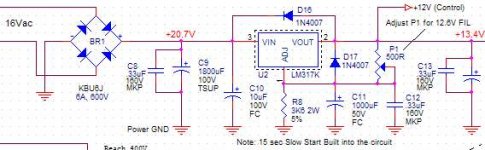
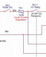
This is the AC input of the equipment. Not shown, first the fuse, then the Power ON switch, then the In-Rush current limiter CL60, the the power transfo.
The heater transfo is connected directly there (Lines going down) and start ramp up immediatly. The filament supply is used to supply a small timer, in this case a simple 555. Then after some delay, it turns on RLY1 to activate the HV supply.
By choosing the 555 delay, you can start the HV after the HTR is fully turn on.
Simple and working quite well. Just to make sure that you choose a relay with contacts strong enough to absorb the HV transfo start-up current. The contacts also need to be rated for 120V in this case.
Have fun.
Attachments
- Status
- This old topic is closed. If you want to reopen this topic, contact a moderator using the "Report Post" button.
- Home
- Amplifiers
- Tubes / Valves
- should the filaments be already hot before the B+ is applied or