I am a newbie and wanted to learn about vacuum tubes.
So, I have bought a few common vacuum tubes (made in USSR) for cheap in Russia.
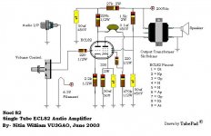
I have stumbled upon this schematic for an audio amplifier online; unfortunetely I could find no documentation for it.
1.What is the estimated current usage and what type of fuse should I use?
2.How should I power 150-160 VDC from 120VAC? Should I use several transformers to step up the power+isolate before being rectified to 0.7x the voltage?
3.How critical should the values of the components be and the stability of the input voltage?-will it still work if it receives 140 or 180 V?
So, I have bought a few common vacuum tubes (made in USSR) for cheap in Russia.
I have stumbled upon this schematic for an audio amplifier online; unfortunetely I could find no documentation for it.
1.What is the estimated current usage and what type of fuse should I use?
2.How should I power 150-160 VDC from 120VAC? Should I use several transformers to step up the power+isolate before being rectified to 0.7x the voltage?
3.How critical should the values of the components be and the stability of the input voltage?-will it still work if it receives 140 or 180 V?
Attachments
If this is the only information you have, you might want to consider finding a different schematic. Important things like the impedance of the primary winding (I) of the output transformer are left out, and I have no way of finding out about the curves of your tube. If you can find a manual or datasheet for that tube, it would help.
I have stumbled upon this schematic for an audio amplifier online; unfortunately I could find no documentation for it.
This you must find from the datasheet of the tube.What is the estimated current usage
You can determine the value of the fuse by calculating the total wattage drawn by the circuit. Multiply the current drawn by the plates by whichever voltage you use (I*V = wattage) and add it to the current drawn by the heater multiplied by the heater voltage. You will want to double this if you're working with stereo. Once you have the wattage drawn, divide it by the primary voltage (120VAC) of the transformer to get the mA of the fuse.and what type of fuse should I use?
Ok, first of all, when you rectify AC voltage, you MULTIPLY the voltage by about 1.414. All you have to do to get around 170VAC is use a diode bridge (google it if you don't know what that is). However, for many reasons, you really want to use a transformer.How should I power 150-160 VDC from 120VAC? Should I use several transformers to step up the power+isolate before being rectified to 0.7x the voltage?
When you shop for power transformers, make sure it has the right windings. You probably want a secondary winding that's equal to the primary voltage, and a filament secondary as well. Your tube information will tell you the voltage you need. Make sure it puts out enough VA (volt-amps, kind of like watts) to power your tubes, and try to overrate it by around 50% to have good headroom. It shouldn't be hard to do this with only two tubes to power.
One other option: You could just buy a 1:1 isolation transformer, again with enough power for the plate draw, and buy a separate 6.3V transformer (or whatever filament voltage you need), again with enough power for the filament current. This might be cheaper, especially if you don't have access to good audio diy stores.
Whichever type you get, if you post some measurements, I can offer you some options for a power supply. Generally it'll be a capacitor-choke-capactor filter, or CLC, that I like to use. Typical input capacitances are around 30-40uF, output anywhere from 40 to 150 or more, and the choke can be anything that can handle the current, voltage, and doesn't drop too much voltage. More henries (H) are better.
In my opinion, you don't need extremely high-quality components, especially if you're just getting into tubes. Try to buy a few more than you need of each in case you fry some things while soldering, in any case it's nice to build up a little stock. If the schematic stipulates 150-60V, you should try to stay within that, especially since the type of transformer that would give voltages in this range is simple (isolation?).How critical should the values of the components be and the stability of the input voltage?-will it still work if it receives 140 or 180 V?
Try this
Similar circuit a bit better laid out for new tube enthusiasts. Easy to read values as well.
Voltage here is a bit higher, a good thing IMHO since it is very easy to find a power transformer to give 200 volts after rectification and filtering.
It appears you need to get some info on building the power supply itself. To that end I recommend downloading PSUD II from Duncan Amps. It is a free power supply simulator which is quite accurate.
Attachments
Ok, so using the datasheets that planet10 has attached, how do I find the total current usage for the tube, excluding the heater? Do I just add up all of the mA values on the datasheet (except the one with 6.3V)?
I was thinking of using two 120-12 VAC@600mA plug in transformers for the psu (120-12-120VAC), but would that be Ok if it would only handle 60mA@120VAC (when converted to primary)?
I was thinking of using two 120-12 VAC@600mA plug in transformers for the psu (120-12-120VAC), but would that be Ok if it would only handle 60mA@120VAC (when converted to primary)?
Attachments

Ih is the heater current, it says 420mA +- 40mA. Let's say 460mA per tube to be safe. .46A * 2 = .92A for the heaters.
Ia for the triode section looks like 13 +- 5mA, so let's say 18mA. That's .036A for both tubes for the triode section.
Ia for the pentode section is 10 +- 5mA, so that's 15mA per tube or .03A for both. Ig for the pentode section is less than or equal to 5mA, so that's .01mA for both.
Total current drawn by the tubes: .996A. You need 76mA or better for the high voltage, and .92A or better for the heaters. I suggest finding a power transformer that puts out around 100mA for the HV and 1A for the heaters.
rouslan said:Ok, so using the datasheets that planet10 has attached, how do I find the total current usage for the tube, excluding the heater? Do I just add up all of the mA values on the datasheet (except the one with 6.3V)?
I was thinking of using two 120-12 VAC@600mA plug in transformers for the psu (120-12-120VAC), but would that be Ok if it would only handle 60mA@120VAC (when converted to primary)?
it looks ok. what are you going to do for the heater currents?
I do not really get it.
-First if I use the adapters for the HV is it adequate for the current load? Do I have to double it like for the heater?
-Why do I have to double the load for the heater when the datasheet just says 420+/-40mA?
What do you mean "per tube"? Doesn't the schematic have just one tube?

-First if I use the adapters for the HV is it adequate for the current load? Do I have to double it like for the heater?
-Why do I have to double the load for the heater when the datasheet just says 420+/-40mA?
What do you mean "per tube"? Doesn't the schematic have just one tube?
rouslan said:What do you mean "per tube"? Doesn't the schematic have just one tube?
It does, but you typically build one for the right channel & another for the left channel.
dave
So with the materials I have:
-HV:2 {120-12VAC@600mA adapters together=60mA@120VAC}+full wave rectif.=170VDC
-Heat.:6.5VAC@650mA
Is it possible to make a mono amp just for probing circuits for sound for the workbench?
How should I stabilize the HV input?-Could I just use high voltage electrolytic caps (like those found in computer psu's) or do I need additional stabilization at the AC end (It will anyway be connected to a power conditioner)?
Just for first time testing, will it work without extra stabilization?
I have some more questions in addition to above.
-Will I need a dummy load when testing it?
-If I test some audio transformers by trial and error (both primary and secondary side) to get the best sound, will this damage the amplifier\speaker?
-Are there any hazardous voltages present on the audio output and how powerful will the output be?
-Will I need a dummy load when testing it?
-If I test some audio transformers by trial and error (both primary and secondary side) to get the best sound, will this damage the amplifier\speaker?
-Are there any hazardous voltages present on the audio output and how powerful will the output be?
rouslan said:...Is it possible to make a mono amp just for probing circuits for sound for the workbench?
Sure, most of us probably do that with a new circuit. Half the expense required to see if we like it!
How should I stabilize the HV input?-Could I just use high voltage electrolytic caps (like those found in computer psu's) or do I need additional stabilization at the AC end (It will anyway be connected to a power conditioner)?
Download PSUDII from Duncan Amps for designing power supplies. For your application I think a CRCRC filter would be sufficient. Use some 100uF caps and some low-value, high wattage resistors (100 ohm 10 watt maybe for one channel).
Just for first time testing, will it work without extra stabilization?
It will probably make sound but you won't be able to gauge the quality of the circuit if you have excessive ripple in your B+. Most likely thing is a loud annoying 100 or 120 Hz hum (depending on your particulary mains frequency).
rouslan said:-Will I need a dummy load when testing it?
Depends on how much you value your speakers (and your ears)! I confess to having connected amps directly to cheap speakers for the first turn-on.
-If I test some audio transformers by trial and error (both primary and secondary side) to get the best sound, will this damage the amplifier\speaker?
That depends on what type of faults the trafos may have. You probably won't do any damage just because the primary impedance is wrong, especially if you are quick on the power switch.
-Are there any hazardous voltages present on the audio output and how powerful will the output be? [/B]
If the circuit is properly constructed the output shouldn't have any high voltage on it.
Output, if well constructed might be 3 watts.
- Status
- This old topic is closed. If you want to reopen this topic, contact a moderator using the "Report Post" button.
- Home
- Amplifiers
- Tubes / Valves
- Audio Amp Project