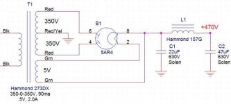
Hi. I want to confirm my design before I buy these expensive transfo and choke. I need a 450-470Vdc supply for my current tube phono preamp project. I want to use a tube rectifier.
This is the front end of the power supply. It is followed by a voltage regulator that set the HV at 420V, tehn a serie of CRC filter. This section is working fine.
My preamp circuit will sink between 5-10ma max.
Please check the following schematic and confirm my parts choice. Thanks for any help or suggestion you can provide.
Here the parts specs and my calculations:
Needed HV: 470-450Vdc at the input of the first HV reg that will regulate at 420V.
The tube rectifier 5Ar4 needs a heater supply of 5Vac, 1.9A.
Transfo selected:
Hammond 273DX, 350-0350V, 90ma, FIL SEC: 5V,2.0A
Choke Selected:
Hammond 157G, 30H, 40ma, 596 ohms, 400V
HV Calculations:
350V * 1.4142 = 495V - 17V drop into tube rectifier = 478V before the CLC filter.
I did a simulation using the Power Supply Designer and using this transfo + tube rectifier specified + CLC filter indicated, I got about 470V at the output.
All the others transfo are too low or too high. I choose the lower rating HV secondary (90ma) to reduce the trasnfo regulation over voltage as far as possible.
This tube rectifier is meeting the HV requirements. It is rated for 550V. And it is easily available.
See the schematic below
Attachments
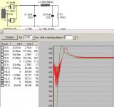
Looking at the simulation, i think its possible to improve the voltage step of the supply. It shows some overshoot.
DHT rob has written an artikel on how to make simulations with psud2, however this is in dutch.
Bas Horneman has translated this into english, and the text can be found in his diymagazine, issues christmas 2005 and 2006 1st quarter. (http://basaudio.net/diymag.htm)
good luck
DHT rob has written an artikel on how to make simulations with psud2, however this is in dutch.
Bas Horneman has translated this into english, and the text can be found in his diymagazine, issues christmas 2005 and 2006 1st quarter. (http://basaudio.net/diymag.htm)
good luck
The heater current available from the transformer in this simple AC configuration should be OK , avoid capacitors across the heater. Startup is the critical time as you point out.
You could measure resistance..er if any ,across the heater filament when cold to then
anticipate current draw. A seperate transformer feeding the heater might be a better long term answer. Also try the William Snyder idea of a suitably rated( voltage) diode in parrallel with the choke acting similar to a low value cap but with better defined switch characteristics. A rectified ground return assembled with a 1000v full wave bridge using AC poles as inputs ie one for audio and the other for DC paths with + and - then connected to actual ground provides some nice isolation and is similar in practice to
isolation benefit arising from dedicated ground planes.
Hope this helps / Chris
Interesting idea to use a rectifier bridge to insulate ground return. I'm using star ground.
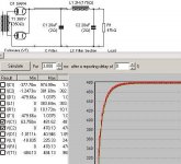
Here my latest simulation. I changed the transfo impedance to more realistic value, and I changed the LC values. Now the voltage goes up faster without overshoot.
I'm still waiting to get a respond from Hammond with the actual transformer parameters (offload voltage, winding resistance, etc) to input the correct values into the simulation. I'm using estimated values for now.
Attachments
If I were you, I'd buy the transformer and make some measurements to enter into your simulation, because they can have a pretty big impact (I speak from experience). Buy the transformer and measure winding resistance, then plug it in and measure unloaded voltage on the secondary. With this information you can estimate the transformer's regulation as well as have lots of detailed information to make your simulation a lote more accurate. If you do do this, and post the measurements, I'll design you a nice cheap capacitor-input choke filter with solid state rectification, assuming you don't mind the "sound" of 1N4007's 
I'll design you a nice cheap capacitor-input choke filter with solid state rectification, assuming you don't mind the "sound" of 1N4007's
1N4007s are VERY noisy. UGH!! The UF4007 is a REASONABLY priced part that directly replaces the 1N4007 and it's MUCH quieter. Also, it's possible to totally squelch the switching noise of the UF4007. Search the Bottlehead Forum archives over on AA for RRSF.
I used 1N's in a linestage of mine and it was quite quiet. I really have no complaints, most of the time the wiring job has more impact on hum than the diode choice. That said, I did buy an octet of smooth recovery ultrafast diodes (mouser # 640-6FLR120) to try out, as well as having a few in TO-220 packages that I salvaged from an old CRT. We'll see. If I have the motivation, I'll try both, but honestly, I'd rather fuss over which music to listen to 
In any case, keep us posted when you get your power transformer, eh algar?
ONE last thing. Instead of going with Solen (although they are a great brand) you might want to try using motor-run oil capacitors. They sound great, from what I've been told, and will look cool mounted on your chassis. Just search eBay for "motor capacitor" and you'll see what I mean.
- Status
- This old topic is closed. If you want to reopen this topic, contact a moderator using the "Report Post" button.
- Home
- Amplifiers
- Tubes / Valves
- Need help for HV section Design