Hi Tubelab,
I read with great interests on your PowerDrive circuit and 833A amp. pages. I am going to homebrew a 805 single-ended power amplifier to drive my dual 15" horn speaker systems.
As far as I know, the 805 is a tube similar to 833A but smaller, and these two tubes have to be run into A2 operation (positive grid bias) to get the maximum power from them. I want to try your PowerDrive circuit. In this connection, I have already acquired IXCP10M45s and 2SK2700ND from digikey already. The 805 and 8K transformers will be ready in one month.
Having read your 833A amp. page, you mentioned that you are going to modify the adjustable -ve grid bias of PowerDrive circuit to adjustable +ve bias to suit the 833A. As I am just a layman to solid state devices, could you kindly share your modified circuit with me? Or are there any PowerDrive boards available for sale from you right now to serve my purpose?
Keep up with your great works!!!
Best Regards,
T.C. MA
Tweeker said:The 805 was specifically desinged for 0 bias operation. You can get quite a bit of power out of an 833 in A1/AB1.
You might want to try something that doesnt normally need a power tube to drive the finals running horns.
I am not sure about the bias of 805, but I have seen a design elsewhere in the internet that it is using +34 volt.
snoopyma said:Having read your 833A amp. page, you mentioned that you are going to modify the adjustable -ve grid bias of PowerDrive circuit to adjustable +ve bias to suit the 833A. As I am just a layman to solid state devices, could you kindly share your modified circuit with me?
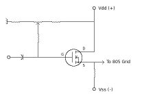
There really is no secret to this. If you need a positive static grid bias, then what you need to do is supply a positive gate voltage to the MOSFET (if it's an N-Channel device, which it probably should be since N-Channel MOSFETs work better than P-Channel devices). The MOSFET is still connected to a +/- supply, however, the source is made positive with respect to ground by having the voltage drop across Rs exceed the magnitude of the (-) supply by the required bias voltage. All that's left is to make certain that there will be enough voltage margin to swing the output of the Source Follower to hit the maximum positive and negative voltages on the 805 grid(s).
See attached for the basic idea. Of course, a power MOSFET will require a gate stopper (ferrite bead --> 1K0 carbon comp resistor --> ferrite bead) and possibly a Zener gate protect diode if one isn't installed on-chip. When dealing with power MOSFETs, you have a naturally high frequency device, and it's very easy to inadvertently make a VHF oscillator.
Attachments
When I experimented with this sort of drive scheme, I found that a Zener Diode was definately a good idea, All the MOSFETS I had access to didnt have a Gate-Zener 'on-chip'...I used a 15V 1/4W type, and mounted it close to the MOSFET (Actually, I mounted it ON the FET)
Also, I found that a 'Gate-Stopper' of 100K was a good value to use to avoid ocillations which MOSFETS are very fond of, and doesnt appreciably affect the HF response of the stage.-On my prototype, I was still at full-power at 100KHz on the grid of the O/P bottles
The 'Bias Supply' to the Pot and then to the Gate of the FET is best if its regulated or at least separate from the normal rails of the driver stage too....A simple zener regulated supply, with good decoupling I found works well....
According to the current and voltages used in your version, Be prepaired to use a suitably large heat-sink on the 'FET, as its quite surprising how much heat can dissipate, even with modest current flow...
All in all, I found the Powerdrive Scheme works very well, Pretty transparent, reliable and delivers the goods.....
I am on a borrowed computer 1200 miles from home now, so I don't have schematics handy. The modification to the PowerDrive circuit to handle the 833A was simple. The original design was made for an 845 or a 211 which requires a negative quiescent voltage on the grid. The original PowerDrive circuit had a voltage divider on the gate of the mosfet (2 resistors and a pot) that went from 0 to - 150 volts. To modify the circuit for the 833A, I simply connected the resistor that used to go to ground to a positive voltage source (I used an external power supply so I could be far away from the 2000 volts when adjusting it).
For your application you need to modify the voltage divider to allow a -50 to +50 volt range of adjustment. You may need slightly different values depending on your plate voltage.
I have no PowerDrive circuit boards available, since each circuit is different, and getting boards made is too expensive for small quantities. The circuit is simple enough that it can be point to point wired. The zener diode mentioned previously is a good idea.
Re: Re: PowerDrive Circuit for 805 (+ve grid bias)
Hello Tubelab.com, Alastair E. & Miles Prower,
Thank you for your replies.
As I am not familar with s.s. devices, I can just get hold of the basic ideas of what you say.
Some stupid questions to ask:
1. For gate stopper, will there be a difference 100K resistor or ferrite bead+1K carbon resistor+ferrite bead technically and sonically?
2. How to install the gate zener (from where to where)? Kindly elaborate.
3. I am going to use the 805 at around 750 plate volts (or higher) and +25 volts grid bias. The plate current will be around 150ma and the grid current is 13ma. Any better suggestion?
4. How can I work out the 2SK2700 to suit this?
Thanks again.
Regards,
T.C. MA
Re: Re: Re: PowerDrive Circuit for 805 (+ve grid bias)
The A Number One problem with power MOSFETs is a high input capacitance. This tends to be much higher than what you find when working with VTs. 100K is excessive since this resistor will combine with the MOSFET's input capacitance to form a low pass filter. Using a smaller resistor with ferrite beads won't cut down on the high audio frequencies so much. The ferrites will help to isolate RF signal paths, and the 1.0K resistor will de-Q the inductance so that VHF oscillations are prevented. The leads at the gate should be kept as short as possible.
From the gate to source terminals. For an N-Channel MOSFET, the Zener's cathode would be connected to the gate, and the anode to the source. Again, connect as directly as possible.
snoopyma said:Hello Tubelab.com, Alastair E. & Miles Prower,
Thank you for your replies.
As I am not familar with s.s. devices, I can just get hold of the basic ideas of what you say.
Some stupid questions to ask:
1. For gate stopper, will there be a difference 100K resistor or ferrite bead+1K carbon resistor+ferrite bead technically and sonically?
The A Number One problem with power MOSFETs is a high input capacitance. This tends to be much higher than what you find when working with VTs. 100K is excessive since this resistor will combine with the MOSFET's input capacitance to form a low pass filter. Using a smaller resistor with ferrite beads won't cut down on the high audio frequencies so much. The ferrites will help to isolate RF signal paths, and the 1.0K resistor will de-Q the inductance so that VHF oscillations are prevented. The leads at the gate should be kept as short as possible.
2. How to install the gate zener (from where to where)? Kindly elaborate.
From the gate to source terminals. For an N-Channel MOSFET, the Zener's cathode would be connected to the gate, and the anode to the source. Again, connect as directly as possible.
- Status
- This old topic is closed. If you want to reopen this topic, contact a moderator using the "Report Post" button.
- Home
- Amplifiers
- Tubes / Valves
- PowerDrive Circuit for 805 (+ve grid bias)