pm, indeed. There should be a "real" 407A (and similar tubes) thread. Somebody else will have to start it, though.
Before that, I do appreciate the Aikido and the flexibility of it. But I like the simplicity of the 407A. The same goes for the 12B4, except I'm not a fan of the "required" regulated PSU. I think the 407A could be ideal for the chip and Class D crowds who want a tube pre, as well as output stage for TDA1543/5-based DACs. I do not doubt it can make for a great phono stage. But personally I would rather look into something like the Siemens C3g.
Arnold, the 01A, 26 and 112A should be fun. But unless you have a private stash somewhere, those prehistoric tubes shouldn't be that easy to locate.
phn, I only have pair of 01A which I got cheap from my friend who has a stash of 01A, 26, and 112 
I'm going to build the 01A soon, but I'm still happy with the 407A (and try the RCA 407A!!) so I need a hard kick in the butt to get going with the 01A pre. However, I plan to run it with either 1k8 (for 2.5mA) or 3K (for 3mA) at the cathode with diyAudio CCS on the plate.
ps.
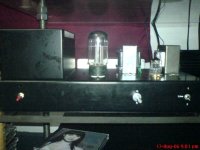
By the way, I had an opportunity to hookup my 407A pre to a pricey system with Mark Levinson (306??) amp + Dynaudio Confidence 3.1 (or 3.3 I can't remember) it replaced a known, expensive brand. The owner was shocked, and was shocked even more when the wife (who was also listening) said "how come that really ugly thing sounds a lot better than your (snip) that is so expensive?" (It was the wife who bought the high-end preamp, upon request of the husband)
After that, I decided to put in my ugly thing, in an even uglier (according to choky) chassis (See photo section)
I'm going to build the 01A soon, but I'm still happy with the 407A (and try the RCA 407A!!) so I need a hard kick in the butt to get going with the 01A pre. However, I plan to run it with either 1k8 (for 2.5mA) or 3K (for 3mA) at the cathode with diyAudio CCS on the plate.
ps.
By the way, I had an opportunity to hookup my 407A pre to a pricey system with Mark Levinson (306??) amp + Dynaudio Confidence 3.1 (or 3.3 I can't remember) it replaced a known, expensive brand. The owner was shocked, and was shocked even more when the wife (who was also listening) said "how come that really ugly thing sounds a lot better than your (snip) that is so expensive?" (It was the wife who bought the high-end preamp, upon request of the husband)
After that, I decided to put in my ugly thing, in an even uglier (according to choky) chassis
(See photo section)Arnold, I just tested Gary Kaufman's circuit in LT Spice. Thanks again for the models, Robert. I have a gazillion LT Spice models so I can just as well learn the program. I had to remove the .47uF input cap or I got really weird readings. mach1 mentioned that already.
The bad thing is that I have learned next to nothing. The good thing is that I know what I need to learn, which should make reading Valve Amplifiers easier.
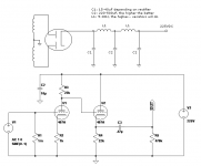
I'm not quite sure what your plate choke design is. It looks like a low-gain stage. I will test it in LT Spice.
The zip file is for the newbies. It includes my spice work file and 407A model.
The bad thing is that I have learned next to nothing. The good thing is that I know what I need to learn, which should make reading Valve Amplifiers easier.
I'm not quite sure what your plate choke design is. It looks like a low-gain stage. I will test it in LT Spice.
The zip file is for the newbies. It includes my spice work file and 407A model.
Attachments
I think I have my final design now.
I'm reading and re-reading The common cathode triode amplifier, chapter 2 of Valve Amplifiers, and scratching my head. Math has that effect on me. I have too many questions. I will settle with one.
Before getting to my question, one of the things I like about the Aikido line stage is that you can get anything from unity to virtually unlimited gain, at least more than what you will never need in a preamp, depending on tubes used.
The cathode somehow relates to the anode of the triode. There's further relation between the anode resistor and voltage. Anyway, by changing the cathode resistor to 2k2 the gain is reduced to just over 16 db. If I change the anode (and subsequent "balancing" cathode) to 18k, it's down to 14 db. That means 14-20 db, or 1:5 to 1:10. This is the main reason I try to understand tube amps--to be able to not just follow a schematic, but to customize it to fit my needs.
Save for the gain, what is the consequence of using a 2k2 cathode resistor instead of 1k, if any? It might be totally irrelevant. But I need to get this question mark out of the way.
I haven't been able to figure out what the 10uF cap is for. Looks like some sort of filter to me. I'll just leave it be.
Attachments
You'll be running the triode section at 2.8mA or so with 6.26V bias. With 1K about 5mA or so with 5V bias.Save for the gain, what is the consequence of using a 2k2 cathode resistor instead of 1k, if any? It might be totally irrelevant. But I need to get this question mark out of the way.
In my experience, running the 407A at 9-10mA is what I prefer
 I'm using TubeCAD to give you the values.
Perhaps no news to most people here, but the 407A is fundamentally different from the 2C51/396A in one regard. Minimum gain for the latter in common cathode configuration (which I think this is) is about 1:20. Higher gain is possible. 1:20 is more or less maximum for the 407A. At least in theory you can go as low as unity.
Upload LT Spice work file and 2C31/396A model for those that care.
Upload LT Spice work file and 2C31/396A model for those that care.
Attachments
Toropkin said:It is very good tube for DAC output, MM phono preamps, etc:
http://astral-for.narod.ru/index/tubes/riaa_fr.gif
http://www.metaleater.narod.ru/45.zip
http://64.233.183.104/search?q=cach...59b40d0dd8+srpp+6n3p&hl=ru&gl=ru&ct=clnk&cd=1[/url]
http://www.tubecad.com/email_2001/e0829/page20.html
I spoke too soon. The 6N3P does indeed look like a great candidate for a phono headamp (just as the C3g). It should be superior to the likes of the 6SN7 and ECC82, perhaps being as good as the E88CC.
I have much to learn about tubes and are likely to be wrong a lot of times. But I didn't want to leave this thread with the risk of having discouraged people from using what seems to be a superior tube, and not least having done it out of ignorance.
The "traditional way" like you said don't tell everything, particulary the frequency response of the tube with the kind of load, is dynamic plate resistance and inter-electrodes capacitances ...Why not try the traditional way? Loadlines and stuff. If you have Morgan Jones, then that pretty much give you everything you need to know.
Why don't you post that 407A linestage and let's see...
FYI, I've made my own 407A pre and I really like it.
With a good simulator, you can do in one little hour the same work that take a week or a month with traditional long and cumbersome calculations and analysis ... Simulators are modern tools for modern peoples, I use them since 1980, my first one was a small "basic language" matrix circuit analysis program running on one of my first computer, a Apple II+ ...
Cheers,
Alain.
Hi mister McLean,Here are 2 models you can try.
* 2C51 LTSpice model
.subckt 2C51 P G K
Bp P K I=(0.0104024146m)*uramp(V(P,K)*ln(1.0+(0.05931576806)+exp((5.058207805)+(5.058207805)*((31.87419992)+
+ (-433.4177162m)*V(G,K))*V(G,K)/sqrt((11.5651995)**2+(V(P,K)-(16.01226163))**2)))/(5.058207805))**(1.510339782)
Cgk G K 2.2P
Cgp G P 1.1P
Cpk P K 1.0P
.ends 2C51
* 407A LTSpice model
.subckt 407A P G K
Bp P K I=((0.01444522184m)+(0.001093484804m)*V(G,K))*uramp((32.37781346)*V(G,K)+V(P,K)+(7.670441457))**1.5
+ * V(P,K)/(V(P,K)+(50.50181836))
Cgk G K 2.2P
Cgp G P 1.1P
Cpk P K 1.0P
.ends 407A
These are in the LTSpice flavour of Spice, since that is what I use personally. If they dont work in B2 spice then other versions can be provided. They were created using CurveCaptor.
I try both of them and it seem there are bugged, parenthesis mismatch and errors in formulas ... So I decide to make my own 6N3P model using the CurveCaptor Andrei Frolov program, it take less time than trying to fix those.
Cheers,
Alain.
I wonder if you are still looking for those models after all those years but yesterday, I was looking for a 6N3P model and I decide to make one myself using the CurveCaptor Andrei Frolov program :I have searcher here, as well as on google, for these models, like you should.
I have found a nice 407A-based line stage. I intend to post it here and let you guys have a say. But I want to play around with it in B2 Spice first. I try to learn B2 Spice as well as tubes.
I have Morgan Jones's Valve Amplifier laying around. I need to learn more about how to work with spice before I start reading it. If I'm to learn anything from the book and not get lost in the lingo and formulas and whatnots, I need a more hands-on approach. Otherwise it will be like reading a math book without solving the problems in it. Currently I suck pretty bad. I did one spice model, which didn't work. Got errors and it couldn't be fixed. When you tried to edit the model, Spice crashed.
Here's the russian datasheet curves I use to make the model :* 6N3P Spice 3F4 Koren 8 parameters model - Mean fit error 0,169309ma
* By Alain Poitras with Andrei Frolov CurveCaptor program
.subckt APK8P6N3P P G K
Bp P K I=(0.005016967051m)*uramp(V(P,K)*ln(1.0+(0.1243074029)+exp((2.145472332)+(2.145472332)*((55.2989605)+(-1022.71849m)*V(G,K))*V(G,K)/sqrt((1.093223372e-006)^2+(V(P,K)-(-11.16773598))^2)))/(2.145472332))^(1.67698976)
Cgp G P 1.6p
Cgk G K 2.8p
Cpk P K 1.4p
RCP P K 1G ; TO AVOID FLOATING NODES IN MU-FOLLOWER
.ends APK8P6N3P
An externally hosted image should be here but it was not working when we last tested it.
Here's the curves I generate with my SIMetrix spice simulator using my new model :
An externally hosted image should be here but it was not working when we last tested it.
Like you can see, some curves extremity are not absolutely perfect but in the usefull parts of the graphic, they fit very well the original ones.
The russian 6N3P is a good but "low cost" tube on eBay !
Alain.

Hello,
I am a bit late, this is the 5670 SPICE model that I tweeked (I adjusted a similar model by Francesco Pintav) and use in B2 Spice. I have built several circuits including the Aikido and went back and forth adjusting the model and confirming that the circuit followed the model and the other way about. If you want send me a PM and I will attach a B2 circuit file in return.
DT
*. 5670_byDT model based on Gut
.subckt 5670_byDT a g k
bout ap k i = ((uramp((v(ap, k)/35.0)+v(g, k)))^1.5)/325
cgk g k 2.2e-12
cga g a 1.1e-12
cak a k 1.0e-12
rleak g gp 10e+3
d1 a ap dx
d2 k ap dx2
d3 pg k dx
.model dx d(is=1.0e-12 rs=1.0)
.model dx2 d(is=1.0e-9 rs=1.0)
.ends 5670_byDT
Last edited:
Hi everybody,
I made many simulation tests with my new "very accurate Koren 8 parameters" 6N3P Spice model and it show me that tube is very good for small preamplifier signal. I test the model with the best operating points I can find for a "conventional commun cathode stage" and for a "commun cathode current mirror stage" which can be made with very handy "current regulator diodes" in series if necessary, a very good high voltage depletion MOSFET like the DN2540 or a big and expensive choke ...
Those tests was done with the maximum output voltage swing for the operation point bias and 100mV RMS input, both with a 1Meg or 100K load. First with a conventional "commun cathode stage" :
Like you can see, with a big output voltage swing, the distortion is a bit high, not like with a 6DJ8 or a 12B4 ... The frequency response is very flat except with a low 100K load at 19,93V output, there is a 1dB loss at 20Khz ... The total harmonic distortion can reach 2,8% at this output voltage.
But at low output voltage ( 2V RMS ), the gain is 19,75 "without bypass capacitor" and the total harmonic distortion is only 0,418% (with a 100K load) at any frequency and there is no high frequency loss.
Now with a current mirror :
All the performances are improved a lot ... The gain is much higher, 35 with a 1Meg load and 29,4 with a 100K load. With a - 2V bias, the output voltage swing can reach 49,51V with a 1Meg load and 41,58V with a 100K load, the distorsion is always lower than 2,2% at this high output voltage. So this tube can make a good driver for a pentode that need a much lower input voltage than that ...
At low output voltage (3,5V and 3V output), the gain is similar but the distorsion is lower than with the conventional "commun cathode stage" ... Below 0,3154% at all frequency and only 0,145% at 20 Hz ... This is very good for a 5$ tube on eBay...
So my verdict is : This tube is really good for small signal and acceptable for medium output voltage power tube driver. The current mirror configuration is perfect for a two stage magnetic phono preamplifier, they usually need a gain of 1000 for 1mV input at 20Hz and 1V output ... The first stage with a high impedance load can have a gain of 35 and the second with a 100K load or a bit less can have a gain of 29 ...
That is a total gain of 1015 at 20H, 101,5 at 1Khz and 10,15 at 20Khz to fit the RIAA curve equalisation. This is perfect for a 10mV magnetic cartridge and 1V output with a 35V "headroom" for very high output cartridge if the supply ia 220V or more, using an adjustable TO220 DN2540 current source ( maximum Vds = 400V ) with a very small heatsink just to keep the case below 45°C ...
Alain.
I made many simulation tests with my new "very accurate Koren 8 parameters" 6N3P Spice model and it show me that tube is very good for small preamplifier signal. I test the model with the best operating points I can find for a "conventional commun cathode stage" and for a "commun cathode current mirror stage" which can be made with very handy "current regulator diodes" in series if necessary, a very good high voltage depletion MOSFET like the DN2540 or a big and expensive choke ...
Those tests was done with the maximum output voltage swing for the operation point bias and 100mV RMS input, both with a 1Meg or 100K load. First with a conventional "commun cathode stage" :
An externally hosted image should be here but it was not working when we last tested it.
Like you can see, with a big output voltage swing, the distortion is a bit high, not like with a 6DJ8 or a 12B4 ... The frequency response is very flat except with a low 100K load at 19,93V output, there is a 1dB loss at 20Khz ... The total harmonic distortion can reach 2,8% at this output voltage.
But at low output voltage ( 2V RMS ), the gain is 19,75 "without bypass capacitor" and the total harmonic distortion is only 0,418% (with a 100K load) at any frequency and there is no high frequency loss.
Now with a current mirror :
An externally hosted image should be here but it was not working when we last tested it.
All the performances are improved a lot ... The gain is much higher, 35 with a 1Meg load and 29,4 with a 100K load. With a - 2V bias, the output voltage swing can reach 49,51V with a 1Meg load and 41,58V with a 100K load, the distorsion is always lower than 2,2% at this high output voltage. So this tube can make a good driver for a pentode that need a much lower input voltage than that ...
At low output voltage (3,5V and 3V output), the gain is similar but the distorsion is lower than with the conventional "commun cathode stage" ... Below 0,3154% at all frequency and only 0,145% at 20 Hz ... This is very good for a 5$ tube on eBay...
So my verdict is : This tube is really good for small signal and acceptable for medium output voltage power tube driver. The current mirror configuration is perfect for a two stage magnetic phono preamplifier, they usually need a gain of 1000 for 1mV input at 20Hz and 1V output ... The first stage with a high impedance load can have a gain of 35 and the second with a 100K load or a bit less can have a gain of 29 ...
That is a total gain of 1015 at 20H, 101,5 at 1Khz and 10,15 at 20Khz to fit the RIAA curve equalisation. This is perfect for a 10mV magnetic cartridge and 1V output with a 35V "headroom" for very high output cartridge if the supply ia 220V or more, using an adjustable TO220 DN2540 current source ( maximum Vds = 400V ) with a very small heatsink just to keep the case below 45°C ...
Alain.
Last edited:
- Status
- This old topic is closed. If you want to reopen this topic, contact a moderator using the "Report Post" button.
- Home
- Amplifiers
- Tubes / Valves
- Need 396A/6N3P/2C51/407A spice model