I have searcher here, as well as on google, for these models, like you should.
I have found a nice 407A-based line stage. I intend to post it here and let you guys have a say. But I want to play around with it in B2 Spice first. I try to learn B2 Spice as well as tubes.
I have Morgan Jones's Valve Amplifier laying around. I need to learn more about how to work with spice before I start reading it. If I'm to learn anything from the book and not get lost in the lingo and formulas and whatnots, I need a more hands-on approach. Otherwise it will be like reading a math book without solving the problems in it. Currently I suck pretty bad. I did one spice model, which didn't work. Got errors and it couldn't be fixed. When you tried to edit the model, Spice crashed.
I think you have got it backwards I would start by reading as much of that Morgan Jones book as possible thereby getting a solid feel for how tubes actually work, and how to apply them in an actual circuit design or spice simulation.
On the Spice front start by downloading some good tube spice models from Duncan Monroe's website or search the threads here for spice models. Once you understand how some of these models work then perhaps you can successful create some of your own.
Incidentally unless you are running something like MCAP8 I find it is better to edit spice models in a text editor, and not spice itself. I use LTSpice (SWCAD3) free from Linear Tech. Works great with tubes and has no node or component limit. Has a somewhat steep learning curve if you are not conversant with spice, and you will have to create your own transformer models.
MCAP8 student/demo edition comes with a limited tube library that is easy to enable and as long as you don't exceed the node limit of 50 nodes the results are quite good.
I would start by reading as much of that Morgan Jones book as possible thereby getting a solid feel for how tubes actually work, and how to apply them in an actual circuit design or spice simulation.On the Spice front start by downloading some good tube spice models from Duncan Monroe's website or search the threads here for spice models. Once you understand how some of these models work then perhaps you can successful create some of your own.
Incidentally unless you are running something like MCAP8 I find it is better to edit spice models in a text editor, and not spice itself. I use LTSpice (SWCAD3) free from Linear Tech. Works great with tubes and has no node or component limit. Has a somewhat steep learning curve if you are not conversant with spice, and you will have to create your own transformer models.
MCAP8 student/demo edition comes with a limited tube library that is easy to enable and as long as you don't exceed the node limit of 50 nodes the results are quite good.
I wasn't trying to be coy. I have no problem giving the people here the schematic. Here's the webpage. I believe it's the first page that turns up when you google 407A line stage.
Nobody would be happier than I if I could read Valve Amplifiers and learn something. Not only would I know tubes, but those five books on Java programming in my bookcase would mean I'm a crack programmer. I'm not. I can get things done, but I would never call myself a programmer. That my semester worth of object-oriented programming in college does. That way I don't have to lie.
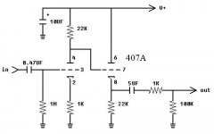
The 22k resistor at the top of one of the tube halves in the 407A schematic sets the gain, I believe. It should be about 28 db. I could look up the name. I won't. That's just the point. I don't need to know what it's called. I only need to know what it does. Should I need to know it by name, I will learn it just as I eventually learned what a method, constructor, etc. are in Java. There's need to force it.
Even with a hands-on approach, I only expect a fraction of what Morgan Jones writes will stick. That's good enough for me. That will give me enough to build on. But just reading it, forget it. I will have read it. But I will have learned nothing.
I upload the schematic as well. It's 250VDC, I believe.
Nobody would be happier than I if I could read Valve Amplifiers and learn something. Not only would I know tubes, but those five books on Java programming in my bookcase would mean I'm a crack programmer. I'm not. I can get things done, but I would never call myself a programmer. That my semester worth of object-oriented programming in college does. That way I don't have to lie.
The 22k resistor at the top of one of the tube halves in the 407A schematic sets the gain, I believe. It should be about 28 db. I could look up the name. I won't. That's just the point. I don't need to know what it's called. I only need to know what it does. Should I need to know it by name, I will learn it just as I eventually learned what a method, constructor, etc. are in Java. There's need to force it.
Even with a hands-on approach, I only expect a fraction of what Morgan Jones writes will stick. That's good enough for me. That will give me enough to build on. But just reading it, forget it. I will have read it. But I will have learned nothing.
I upload the schematic as well. It's 250VDC, I believe.
Attachments
Person phn = new Person("phn");
try {
phn.read(Books.getAuthor("Morgan Jones").getBook("Valve Amplifiers"));
} catch (SlackerException ex) {
ex.printStackTrace();
System.err.println("Crack the darn book, then tell us what you think about it. It really is a good book.");
phn.dispose();
System.exit(-1);
} catch (SpiceCrashedException ex) {
phn.dispose();
System.exit(-1);
} catch (IWontLookupTheNameException ex) {
phn.dispose();
System.exit(-1);
} catch (INeverLearnAnythingException ex) {
phn.dispose();
System.exit(-1);
} catch (IAmNotAProgrammerException ex) {
System.out.println("Not everybody is.");
phn.dispose();
System.exit(-1);
}
phn.setIntelligence(phn.getIntelligence()++);
return true;
phn,
I would ditch the input capacitor, ditch the 1k resistor after the output capacitor and change the resistor from output capacitor to ground to from 100k to 1M.
While you are at it calculate an appropriate value for the output capacitor based on the following formula.
c = 1/ (6.283 r f)
where c is the capacitance in farads, r is the input impedance of your power amp in ohms, and f is the -3db frequency you are aiming for in Hz (commonly 5Hz, but you can put it lower if coincides with LF poles in your power amp).
Oversized coupling caps are costly in terms of $ and performance.
See Gary Kaufman's website for a build of the circuit. I believe he constructed it as per the circuit diagram.
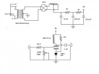
Personally, I would go for this John Broskie circuit instead, which is extremely well thought out.
pm
I would ditch the input capacitor, ditch the 1k resistor after the output capacitor and change the resistor from output capacitor to ground to from 100k to 1M.
While you are at it calculate an appropriate value for the output capacitor based on the following formula.
c = 1/ (6.283 r f)
where c is the capacitance in farads, r is the input impedance of your power amp in ohms, and f is the -3db frequency you are aiming for in Hz (commonly 5Hz, but you can put it lower if coincides with LF poles in your power amp).
Oversized coupling caps are costly in terms of $ and performance.
See Gary Kaufman's website for a build of the circuit. I believe he constructed it as per the circuit diagram.
Personally, I would go for this John Broskie circuit instead, which is extremely well thought out.
pm
Attachments
ethermion, I have read the first chapter. Half I know about electronics I learned from that. So, yes, it's a very good book. It's probably as good as a book of its kind can get. But without some prior knowledge, I don't think it would be nearly as easy to read. The Square waves and transient section just went over me. It's not a long piece, but halfway through it everything I read was just noise. There was no revelation. No nothing. Total information overload.
By the way, I haven't read five books on Java. Nobody reads something like Java in a Nutshell. I have never learned anything useful from a book on Java, anyway. What I know about programming I have learned from hands-on experience and hammering it in. Don't mistake this for arrogance. But I have no real or genuine interest in programming (or math or electronics) so it has never come easy to me.
Cool. Z is a constant pain for me. PSRR I have to look up. It's not that it's the first time I see it mentioned. It's just that it's Greek to me.
I thought the 1k resistor, or a lower value, say 100R, would be beneficial. Just as the 100k. To quote Frank:
"What you're describing is due to the added gridstopper (more detail), the output R tames a mild overshoot (way above what's commonly believed being the audio band BTW) and the 100K pulldown resistor forces more constant current draw. The latter brings you better dynamic range, audibly so in most cases."
Most DIY pre/line stages have a 1M resistor on the output. I know I miss something fundamental here, but I thought the idea was to shoot for lowest possible Z. Other than what Frank wrote, it should also make the system less cable dependent.
The 5uF cap is indeed another thing that bothers me. I would like to use a more civil 2.2 uF cap, or less.
The circuit is Gary Kaufman's.
The Aikido does interests me as well. As does the 12A4-based line stage found in a long thread here.
I guess I was more surprised not finding a model than anything else. Thought the 396A/6N3P/2C51/407A (and equivalents CV2831, 6385, 6854, 6CC42, 18C51) would be popular enough.
By the way, I haven't read five books on Java. Nobody reads something like Java in a Nutshell. I have never learned anything useful from a book on Java, anyway. What I know about programming I have learned from hands-on experience and hammering it in. Don't mistake this for arrogance. But I have no real or genuine interest in programming (or math or electronics) so it has never come easy to me.
arnoldc said:
PSRR is -14.4dB, Output impedance is 4.2K, 4.3Hz to 183kHz at -3dB
Cool. Z is a constant pain for me. PSRR I have to look up.
It's not that it's the first time I see it mentioned. It's just that it's Greek to me.mach1 said:phn,
I would ditch the input capacitor, ditch the 1k resistor after the output capacitor and change the resistor from output capacitor to ground to from 100k to 1M.
While you are at it calculate an appropriate value for the output capacitor based on the following formula.
c = 1/ (6.283 r f)
where c is the capacitance in farads, r is the input impedance of your power amp in ohms, and f is the -3db frequency you are aiming for in Hz (commonly 5Hz, but you can put it lower if coincides with LF poles in your power amp).
Oversized coupling caps are costly in terms of $ and performance.
See Gary Kaufman's website for a build of the circuit. I believe he constructed it as per the circuit diagram.
Personally, I would go for this John Broskie circuit instead, which is extremely well thought out.
pm
I thought the 1k resistor, or a lower value, say 100R, would be beneficial. Just as the 100k. To quote Frank:
"What you're describing is due to the added gridstopper (more detail), the output R tames a mild overshoot (way above what's commonly believed being the audio band BTW) and the 100K pulldown resistor forces more constant current draw. The latter brings you better dynamic range, audibly so in most cases."
Most DIY pre/line stages have a 1M resistor on the output. I know I miss something fundamental here, but I thought the idea was to shoot for lowest possible Z. Other than what Frank wrote, it should also make the system less cable dependent.
The 5uF cap is indeed another thing that bothers me. I would like to use a more civil 2.2 uF cap, or less.
The circuit is Gary Kaufman's.
The Aikido does interests me as well. As does the 12A4-based line stage found in a long thread here.
I guess I was more surprised not finding a model than anything else. Thought the 396A/6N3P/2C51/407A (and equivalents CV2831, 6385, 6854, 6CC42, 18C51) would be popular enough.
Attachments
spice models
Here are 2 models you can try.
* 2C51 LTSpice model
.subckt 2C51 P G K
Bp P K I=(0.0104024146m)*uramp(V(P,K)*ln(1.0+(0.05931576806)+exp((5.058207805)+(5.058207805)*((31.87419992)+
+ (-433.4177162m)*V(G,K))*V(G,K)/sqrt((11.5651995)**2+(V(P,K)-(16.01226163))**2)))/(5.058207805))**(1.510339782)
Cgk G K 2.2P
Cgp G P 1.1P
Cpk P K 1.0P
.ends 2C51
* 407A LTSpice model
.subckt 407A P G K
Bp P K I=((0.01444522184m)+(0.001093484804m)*V(G,K))*uramp((32.37781346)*V(G,K)+V(P,K)+(7.670441457))**1.5
+ * V(P,K)/(V(P,K)+(50.50181836))
Cgk G K 2.2P
Cgp G P 1.1P
Cpk P K 1.0P
.ends 407A
These are in the LTSpice flavour of Spice, since that is what I use personally. If they dont work in B2 spice then other versions can be provided. They were created using CurveCaptor.
phn,
the 1k 'gridstopper' is not a gridstopper at all as it is on the output cathode. Ultrasonic ringing on the output can be a problem with transformer coupled linestages that can be addressed by loading, but is not usually an issue with regular RC coupling. The gridstoppers shown on the Broskie circuit should tame any tendency towards RF misbehaviour.
I fail to see how the 100k 'pulldown resistor' could promote a more constant current draw, as all DC is effectively blocked from flowing through it by the 5uF output capacitor. The Broskie circuit, however, has been carefully designed to achieve this outcome under dynamic conditions by balancing the ratio of the resistors used to bias V1 with those for V2. If you check you will find that the sum of the resistance for V2 = approx 0.9 that for V1 (as far as the power supply is concerned V1 and V2 are in antiphase, and the 0.9 ratio adjusts for the cathode follower gain of 0.9)
If you use a 1M output resistor the input impedance of your power amp will be the primary determinant of the impedance the preamp sees, and (unless the power amp input impedance is quite low) you will therefore be able to use a smaller coupling cap.
Having said all this, If I were in your place I would probably go for the aikido which is a later and probably more effective design.
Arnold, the diode in the circuit fulfils a protective role only and has nothing to do with the performance of the linestage. Unfortunately, the link to the circuit no longer exists, so everthing I have stated here is from memory.
pm
Robert, I use B2 Spice Lite. I found it more intuitive (read simple) to use than the others I tried. But these models will probably do anyway. These are problems I think I can solve, as well as allow me to, hopefully, learn something. I assume most models around are not designed for B2 Spice anyway. Thanks for the models.
pm, I just fell in love with the 407A. I'm not really a fan of preamps. I prefer passive/transformer pre/line stages, meaning basically a volume pot. But they have their problems. I might go Aikido later. I'm still scouting.
Grid stopper? I'm learning, I'm learning.
arnoldc, Thanks. It would have been nice with a 407A tread here like the one on the 12B4.
arnoldc, Thanks. It would have been nice with a 407A tread here like the one on the 12B4.
let's make this one
I'll post my simple 407A (and cousins) schema once I get my non-work related USB drive connected on my notebook.
PSpice models for Russian tubes are here:
http://www.next-power.net/next-tube/ru/libs.php3
(file PSlib.zip)
http://www.next-power.net/next-tube/ru/libs.php3
(file PSlib.zip)
"I have a pair of russian 6N3P tubes and I`d like to use them in the line stage...
Anyone knows are these tubes used in audio and where. I tried a simple (RC) stage and they sounded cold and chrisp...
any schematics?"
It is very good tube for DAC output, MM phono preamps, etc:
http://astral-for.narod.ru/index/tubes/riaa_fr.gif
http://www.metaleater.narod.ru/45.zip
http://64.233.183.104/search?q=cach...59b40d0dd8+srpp+6n3p&hl=ru&gl=ru&ct=clnk&cd=1[/url]
http://www.tubecad.com/email_2001/e0829/page20.html
I haven't tried the 6N3P yet, but since you have it in prototype already, try 160V anode voltage and 9mA. 2V - 4V bias to suit your taste.
How are you operating it right now?
My friend just finished his 407A pre and told me his 26 pre beats it in openness, but the 407A pre beats the 26 pre in bass (tighter) and highs (cleaner). He's running his at 11mA.
How are you operating it right now?
My friend just finished his 407A pre and told me his 26 pre beats it in openness, but the 407A pre beats the 26 pre in bass (tighter) and highs (cleaner). He's running his at 11mA.
phn, mach1,
my friend emailed me his 407A circuit which he finished last night.
he comments that,
1. "this is very likeable"
2. "when the led current was around 7ma it was a bit edgy but now at around 11mA its smooth"
3. "B+ around 165 i think if i use 5V4 around 175"
4. "1.9V" (when I asked for the bias voltage)
5. "but like this better than the (snipped) specially on vocals"
6. "(snipped, censored) bass!!" when I asked him what is the strongest character.
7. but he goes on to say, "deep musical but for me its great for vocals"
I asked him, compared to your 26?
1. "the 26 more airy. but the 407 is not lean ha."
2. "mids can fill up the whole room. mid highs are snappy. without being hard"
3. "overall i would say its better than my 26 by a hair. maybe if i try the 01A or the UX-112"
Attachments
- Status
- This old topic is closed. If you want to reopen this topic, contact a moderator using the "Report Post" button.
- Home
- Amplifiers
- Tubes / Valves
- Need 396A/6N3P/2C51/407A spice model