Hello,
Newbies questions to you guys.
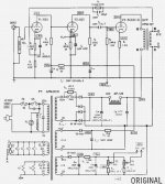
If I want to hook up both "plate" of 6c33 to the output transformer in parallel and this tube has only one Cathode.
- Is it possible to do this with out harming the tube ?
- If yes, which connection do I need to change in this schematic and what is the proper value on the primary side of Output transformer ?
.... and the last question, is 6J5 still able to drive them ?
Not sure if my explanation is clear enough, sorry for poor english.
")
Newbies questions to you guys.
If I want to hook up both "plate" of 6c33 to the output transformer in parallel and this tube has only one Cathode.
- Is it possible to do this with out harming the tube ?
- If yes, which connection do I need to change in this schematic and what is the proper value on the primary side of Output transformer ?
.... and the last question, is 6J5 still able to drive them ?
Not sure if my explanation is clear enough, sorry for poor english.
Attachments
Hi,
The 6C33C consist of 2 triodes in the same envelope but they are connected in parallell internally. There is no way to separate the 2 triodes from each other to use it as 2 triodes. There are 2 separate heaters and the tube can be powered with either one or both heaters the performabnce will be much less when using only one heater so use both.
A 6J5 is enough to drive a 6C33C, the Miller capacitance is about 100pF and a 6J5 will have about 5kohm output impedance which will give a -3dB point of ~300kHz
Recommended load impedance of 6C33C is 600 ohm and operating point of 220V and 200mA so you schematic is spot on, I believe it is one of the original ones published in MJ in Japan.
Regards Hans
100db,
On the socket there is only one Anode pin in 4
It's just because you heat with the 2 heaters that you get the maximum
of power from this tube, if you use only one of the heaters you'll work
with half the tube...
Heaters are on Pins : 1 to 2 and 6 to 7
Kathode on pin 3
Anode on pin 4
Gate on pin 5
Thats a total of 7 pins.
PS: I am working on the http://www.valvediy.com/simplexpg1.html
Regards.
Alain.
100db,
Thanks, but for the amplifier on the link, it's from Ari Polisois !
I am building a "Complex" version with 2 sets of separated power supply's ;
one for each channel, and each individual PS's are MosFet regulated from
a 330VA toroid transfo.
2 Toroid transfo's 330VA
and for each:
1 alim for B+ 200 to 270 Volts DC at 0.9A Plate 6C33C-B
1 alim for 6SN7GTB to 420 Volts DC at 80 mA Driver
1 alim for 6SN7GTB to 200 Volts DC at 50 mA Preamplifier
1 alim for 6C33C-B heaters to 12.6VDC 3.3A
1 alim for 6SN7GTB heaters at 12.6VDC 1A Driver
1 alim for 6SN7GTB heaters at 12.6VDC 1A Preamplifier
1 Alim for LCD display 5VDC at 0.5A
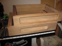
I just finished the 2 walnut chassis!
Alain.
Thanks, but for the amplifier on the link, it's from Ari Polisois !
I am building a "Complex" version with 2 sets of separated power supply's ;
one for each channel, and each individual PS's are MosFet regulated from
a 330VA toroid transfo.
2 Toroid transfo's 330VA
and for each:
1 alim for B+ 200 to 270 Volts DC at 0.9A Plate 6C33C-B
1 alim for 6SN7GTB to 420 Volts DC at 80 mA Driver
1 alim for 6SN7GTB to 200 Volts DC at 50 mA Preamplifier
1 alim for 6C33C-B heaters to 12.6VDC 3.3A
1 alim for 6SN7GTB heaters at 12.6VDC 1A Driver
1 alim for 6SN7GTB heaters at 12.6VDC 1A Preamplifier
1 Alim for LCD display 5VDC at 0.5A
I just finished the 2 walnut chassis!
Alain.
Attachments
- Status
- This old topic is closed. If you want to reopen this topic, contact a moderator using the "Report Post" button.