So it didn't follow the original schematic? Then it is not a true Williamson amplifier.
It did follow the original schematic. A slightly different, if not improved, power supply doesn't disqualify it as a true Williamson.
John
Yes, I agree. To me, a Williamson-style design consists of a single-ended input stage, concertina splitter, push-pull driver and push-pull output tubes. That's it; any amp with this basic topology is a Williamson-style amp, as far as I am concerened
Using modern components that were unavailable in the 1940s seems fair enough, as does a choke input filter.
UL topology is fair enough, too, IMHO.
I would argue that a driver with separate cathode resistors instead of a shared resistor, such as we might do if we want to apply an inner feedback loop to the driver cathodes, is still pretty close to a Williamson design.
Even using pentode/cascode/SRPP/mu input stage, instead of just a triode, does not make it non-Williamson to me.
Of course, at some point in changing the design, it won't be 'Williamson' any more.
Ok, so I still have the single-ended input stage. the concertina splitter, push-pull driver, and push-pull output tubes. I only did some work on the psu and modified the output section into a fixed bias type.
So my amp is still a Williamson-style at first glance.
That article is making my knees shake.
SY,
That's exactly what I did in my implementation.
So my amp is still a Williamson-style at first glance.
That article is making my knees shake.
A simple change of one of them by a decade fixes that problem very nicely.
SY,
That's exactly what I did in my implementation.
JojoD818 said:That article is making my knees shake.
It need not. Stanley White is pushing an agenda, and making the Williamson sound worse than it really is is self-serving to say the least.
The Williamson phase inverter was a split load phase inverter. The plate and cathode resisters of the second section of the 6SN7 were matched at 47 Kohm resisters. This balances the amplitude of the inverted signal (as long as the load resisters don't drift with time), but there is a hidden serious flaw, not dealt with by producers of the Williamson amplifier. The plate impedance and the cathode impedance are not of the same value even though the load resisters are the same. This means that at high frequency, the output of the phase inverter is no longer balanced.
What he doesn't get around to mentioning is that this unequal impedance imbalance doesn't begin to appear until the signal frequency is several hundred KHz. So don't use a split load for that DC-to-daylight, wideband o'scope vertical deflection amplifier. In the audio band, it doesn't make any difference unless the load impedances go unbalanced if the next stage overdrives and starts to pull grid current. Williamson fixed that by moving it back to a low level stage in the front end.
The main problem with the classic Williamson wasn't in the topology, but rather the implementation. 20db(v) of gNFB is way excessive. That, in turn, arose out of the "Spec Wars" that rage on to this very day. Crowhurst and Cooper in High Fidelity Circuit Design (1956) devote four chapters to describing theoretical design methodologies and neat little tricks with interstage coupling in order to get some stability in a design that uses 20db(v) of gNFB. Crowhurst obviously knew better than that, but being a design consultant to the "Big Box" manufacturers, he couldn't exactly spill the beans concerning the Spec Wars, lest he find himself unemployed and persona non grata in the industry. A VT amp doesn't need that much gNFB (unless you are overcompensating for a fundamentally poor open loop design). I did a design for an 807 amp that includes an inner feedback loop of 6.95db(v) NFB from the 807 plates to the drivers. Even with 12.2db(v) of gNFB, that sounded hideous: very "solid statey", considerable loss of detail, loss of clarity to vocals, no sound stage at all. 4.0db(v) of gNFB was all it took to clean up the remaining pentode nastiness, and give an improved damping factor for bass with "authority", but no underdamped slopppiness. I'm sure "the numbers" are worse, but "the numbers" do not always tell all.
What he doesn't get around to mentioning is that this unequal impedance imbalance doesn't begin to appear until the signal frequency is several hundred KHz.
Does it even appear then? That would seem to violate Kirchoff's Law as long as the loads at each end are equal.
SY said:Does it even appear then? That would seem to violate Kirchoff's Law as long as the loads at each end are equal.
It doesn't violate the KVL since the reactance of device capacitance starts becomming of the same order of magnitude as the combined Rl || r(p) || Rp resistance. That, in turn, causes the effective load impedances to become unbalanced. If you use reasonable VTs with r(p)'s under 10K (almost always the case, especially when the cathodyne is the last front end stage) the fisrt critical frequency appears at around 100 -- 300KHz. A second critical frequency due to the lower cathode source impedance occurs > 1.0MHz.
This is why you don't see cathodynes being used as splitters for wideband o'scope deflection amps. These are almost always either LTPs, or some topological variation on the LTP theme to improve balance at extreme frequencies.
SY said:Sorry, I'm not following that. Are you talking about the internal capacitances of the split load tube?
The sum total of capacitance would include Cpk of the phase inverter + Cmiller + Cgk + Cstray of the driven stage. Ideally, the input capacitances coming from the two driven VTs would be equal (but never are) and, of course, Cstray is neither predictable, nor identical. It's the different Zo's of the plate circuit and cathode circuit that experience imbalance due to these capacitances. If you can keep the equivalent plate load reasonable, any distortion effects can be delayed until you hit the 100+KHz signal level. There's precious little of that from most audio sources anyway.
Sometimes you can partially compensate by making your split load from a pentode (lower device capacitance -- can perform up to several MHz if done right) or by adding a compensating pole to the cathode circuit by adding a small amount of NFB across a small (~100pF) coupling capacitor. This was done with some Williamsons to improve HF stability under that horrendous gNFB that they insisted upon to score points in the Spec Wars.
In the driven stage, wouldn't you expect to see the Cmiller+Cgk completely overwhelm the Cstray? Figure that Cm+Cgk would be of order of 40pF for a 6SN7, Cstray might be 2pF, delta Cstray maybe even smaller. So even in that case, things are balanced to well over a megahertz, taking into account the slight imbalance in interelectrode capacitance in 6SN7s.
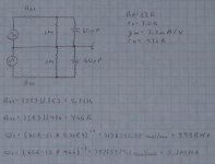
I doubt that you can get Cstray much under 30pF. 2.0pF is way unrealistic. Anyway, if you use a 6C4 for a cathodyne splitter (entirely reasonable) with Rp= Rk= 22K, with r(p)= 7.0K, and g(m)= 2.1mA/V (again, reasonable, though a bit optimistic in that this will require a very large Vpp unlikely to be used for the more common audio VTs like 6V6s, 6BQ5s, 6AQ5s, etc.) The situation could be worse. Assume a combined capacitance of 60pF (entirely reasonable). That gives a plate source impedance of 5.31K, and a cathode source impedance of 476R. You get two critical frequencies: 499KHz, and 5.7MHz. Even a decade below this, you still have 49.9KHz as a likely problematic frequency, and that's still beyond the audio band (although it might figure in HF stability under gNFB). The second is so far beyond audio that it's ignoreable for all practical purposes. In the audio band, any imbalance from normal component error will be greater.
Even under less than ideal situations (lower Ip's; higher r(p)'s; lower g(m)'s) the situation isn't going to deteriorate all that much. I wouldn't expect a critical frequency here under 100KHz in any case.
Even under less than ideal situations (lower Ip's; higher r(p)'s; lower g(m)'s) the situation isn't going to deteriorate all that much. I wouldn't expect a critical frequency here under 100KHz in any case.
Attachments
I doubt that you can get Cstray much under 30pF. 2.0pF is way unrealistic.
With all due respect, I think that's incorrect. And double-checking some of Morgan Jones's calculations in Valve Amplifiers, he uses roughly the same number I do. See, for example, the Bevois Valley amp and the calculation for the 75us time constant for his RIAA stage.
Just for fun, I happen to have the input stage for a Red Light District build sitting on my bench. It's got a split load inverter using a 12AT7. I'll hook it up to a 6SN7 and see what we get. Experiment trumps assertion every time!
OK, I set up a 5692 (6SN7 equivalent) with a pair of red LEDs in each cathode. Attached to the RLD board (with the 12AT7 split-load) with about two inches of wire for each side. CCS plate loads set for 10mA. Basically, this was the already-built test jig I used in some 5692 measurements I posted here a while back, saving me a lot of work!
Anyway... I only have capability to measure to 1MHz (signal generator limit), but saw no imbalance to that point, and damn little rolloff (10% or so, might have been from the first stage).
I think there's a problem with your equivalent circuit, namely the way you divided up the generator and grounded the center. If that were so, the splitter wouldn't balance at all.
edit: I revisited the measurement and found a mistake. The actual f3 is closer to 300kHz, but as before, the HF balance is still within measurement limits up to 1MHz.
Hi,
Always when lokking at the split load phase inverter it is important to see it for what it is and how it is supposed to work, i.e as a phase splitter, to analyse cathode and anode separately for output impedance and frequency response doesn't work as both outputs are loaded in normal operation. The output impedances from cathode and plate are equal when both outputs are equally loaded as have been described by Morgan Jones in the 3rd edition of his book and also eartlier by Preisman.
If you do a spice simulation you will end up with 2 poles that are very close to each other, in my OTL amp the 2 poles are at 8.875MHz and 8.516MHz according to the simulation with the only difference in loading being that the phase splitter tube have a Cga of 0.5pF and a Cgk of 3.2pF, (12BH7). The frequencies make sense as the output impedance of the split load with my values should be ~280ohm which give a load capacitance of ~65pF which seems reasonable in my design.
So the split load stays balanced up to very high frequencies and that the only unbalance comes from the differences between Cga and Cgk, (given of course that the load impedances are equal)
Regards Hans
- Status
- This old topic is closed. If you want to reopen this topic, contact a moderator using the "Report Post" button.
- Home
- Amplifiers
- Tubes / Valves
- Interesting Williamson article..