I would like to share some ideas I developed to prototype a circuit. The name 'euro barrier strip palace' comes from the 'crystal palace': Morgan Jones used lots of glass - I use lots of euro barrier strips. The resemblances are stopping here, as I have much to learn from Morgan Jones.
Attachments
I will try to explain the way the prototype is put together.
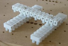
The base: attached to the perforated plate, also does the ground job (the 1,5mm2 wire thorugh the holes of the strip is missing).
During mounting the whole circuit is supported through two extra euro barrier strips. When finished it is transferred to a – earthed – perforated aluminum plate. Only problem it is a bit to thin but it has got sufficient holes to attach everything you want (an extra decoupling capacitor, another tube module, a regulator).
Attachments
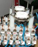
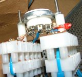
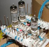
The tube module. Formed by two euro barrier terminal strips. The lower one has six wires attached to it that will be used to feed filaments, B+, ground, B- and a second B+ (regulated B+ for screens in a pentode). The upper one has, from left to right, an open connection, than the grid, cathode, grid2 (pentodes) and plate, and finally another open connection. The idea is that this order will be kept will all modules. I made ready to use tube modules for the EL84/PL84, EL34/KT88…, EF86, ECC family and octal double triodes. The tube modules are attached (through copper bars) to the plain module or CCS module. Lots of wires on them and I regret I didn’t buy 6 different colors – what would make the identification much easier. For most circuits you will not need all of them, but I wanted to be sure I would always have enough. Drawback is that in this arrangement the filament supplies MUST BE DC regulated.
Attachments
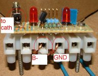
The circuit module. Each of those is made for a different circuit. For the moment I just made them for the red light district (or similar) and the baby huey (but already have the plans ready for aikido, crystal palace, mu stage, WCF, mu follower). They are fit straight into the tube modules (through 1,5mm2 solid core copper wire). As the different tube modules all have the same connection order for grid, cathode, grid 2 and plate, it is possible to use the same circuit module with different tubes.
AND
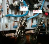
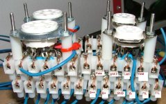
The tricky part…connection of components. I bought some good quality alligator clips, drilled the pin out and put a copper rod in place. Those are fitted on the circuit module. It may not be clear from the picture, but no alligator clip can touch an adjacent one: either they are insulated or just mount in a way it is impossible to touch. With components in place (as shown on the picture) they hardly move – the whole thing seems pretty steady. The larger components (as capacitors) I am planning to hold in place with elastic, so that the alligators are just there to make the electrical contact.
AND
The tricky part…connection of components. I bought some good quality alligator clips, drilled the pin out and put a copper rod in place. Those are fitted on the circuit module. It may not be clear from the picture, but no alligator clip can touch an adjacent one: either they are insulated or just mount in a way it is impossible to touch. With components in place (as shown on the picture) they hardly move – the whole thing seems pretty steady. The larger components (as capacitors) I am planning to hold in place with elastic, so that the alligators are just there to make the electrical contact.
Attachments
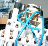
The euro barrier strips I got from the shop with building material. They cost 60 eurocents each (with 12 connections), not much, but with the quantities I bought… (I also use them as pure building blocks, to hold capacitors in power supplies, for gainclone prototyping and so on). The bolt inside euro barrier strips will break stranded wire. So, where I use stranded wire (always a minimum of 0,75mm2) I tinned the ends that will go into the euro barrier strip. For the circuit module I used 1,5mm2 solid core throughout – this has: i) good electrical conduction, ii) can’t be broke through the strip and iii) will never make a loose fit inside the strip (given the bolt is fit tightly). I can fit up to 3x 1,5mm2 inside each strip (which is made for 6mm2). I believe that the use of thick, solid core wire, makes up for the increased size of the circuit when mounted this way.
The picture shows the connection of the base, the CCS module and a tube module.
The picture shows the connection of the base, the CCS module and a tube module.
Attachments
I also made some tube modules with ‘loose ends’ to be used by all other noval valves. This allows more flexibility, but connections get longer. I also would like to keep a resistor soldered in each contact, so that for any tube I can use a grid stopper. I still have to attach wire to the 'lugs' of the resistors.
Attachments
SY said:Insanely cool!
Hi SY
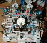
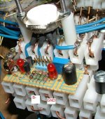
The first picture shows my version of yours red light district. For the moment I am just using resistor + capacitor on the cathodes - I still have to buy the LED's. And well, it plays, no hum whatsoever.
Erik
SY said:It looks like the Borg Collective.
Somewhere there is a joke about using the LEDs for bias rather than a resistor because, well, because resistance is futile ...
4 section Euro Terminal Black
For those interested I have some 4 section Euro
Terminal blocks. Have about 2000 in stock
There --- 3 for $1.00
http://www.apexjr.com/images/EUROTERMINALBLOCK1.jpg
Steve @ Apex Jr.
For those interested I have some 4 section Euro
Terminal blocks. Have about 2000 in stock
There --- 3 for $1.00
http://www.apexjr.com/images/EUROTERMINALBLOCK1.jpg
Steve @ Apex Jr.
- Status
- This old topic is closed. If you want to reopen this topic, contact a moderator using the "Report Post" button.
- Home
- Amplifiers
- Tubes / Valves
- Euro barrier strip palace