Hello! I re-wired my El34 SE amp for Triode mode (it just sounds better!) and I took some readings after the amp had been going somewhat loudly for 40 minutes or so. the problem is that I don't quite understand if these numbers are normal, or ab-normal
after 40 minutes of playing music:
Supply Voltage 420v
Voltage across plate 414v R-ch 415v L-ch
Load Resistance 2.5Kohm primary 8ohm Secondary
Cathode Bias resistor 500ohm
Voltage across Cathode Bias resistor 13v
Current ~26ma?
Both El34s has Blue Glow on the glass
Do these numbers seem out of whack? or is my Amplifier on the Road to glory?
You need to measure the plate current in UL or pentode mode, whichever mode it initially used.
Your operating point seems to have shifted towards cut off - I would normally expect there to be somewhere around 30V on the cathode resistors. Where did you connect the screen grid to? (They should be connected to the plate through a small resistor say 100 - 1K)
IMO I have never observed a large shift in operating point with EL34 switching from UL mode to triode mode, however I have never run them with cathode bias.. So I am puzzled.. What value are your grid resistors (large??) and is there a voltage developing across them - aka grid leak bias? Could be the case if they are gassy. Some dull blue glow on the glass and around the screen grid is normal with modern relatively soft vacuum EL34, bright blue glow that fills the space between the electrodes and generally around the envelope is a sign of excessive gas.
The amp probably isn't going to blow up, but the operating point sounds wrong. You need to investigate further and how about posting a schematic.
The voltage seems high for an EL34 SE. The numbers I have around here indicate a more "normal" value is 350V on the plate.
Also, 26mA seems almost loafing for an EL34. In SE class A they can go to about 70mA. Lowering the B+ to 350 or so and changing Rk to 360 ohms would be more in line with hi-fi use.
What you have might work great and last a long time, EL34s are pretty solid tubes in general I think. I've been thinking of building an EL34 SE since I have all the pieces and the numbers I suggest are just the values I came up with.
I only have experience with new, Russian EL34 tubes and only a very small sampling of those (4) but they have all had a blue glow near the base. I think that is just normal for those tubes.
Hi Alex,
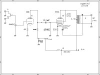
Nothing appears to be amiss in that schematic, are you sure that the 13V reading you got was correct. I see nothing in the design that would inherently account for the weird reading you mentioned.
Dumb question - meter set to AC?
Also with the triode connection you probably don't need to connect the cathode bypass to the top of the secondary for the little bit of feedback it provides. And are you sure the feedback is not positive?? I'd just ground the cap directly. I'd definitely add some smaller film bypass caps or replace with 51uF Solens.
250K grid resistor seems reasonable for an EL34 - are you sure that the output stage is not oscillating? I recommend adding a 1K grid stopper right at pin 5 of the EL34. I have had these oscillate in the VHF region at a time when I didn't have a scope that could "see" it.
It was most definatly set on DC,
Which do you recomend I try first?
I think I am going to ground the cap before I put in a stopped resistor purely because its a very easy modification
Is there anyway I could see if the amp is ocsilating? I don't have a scope, I do have a radio that can do AM/FM/LW/SW1-9 and a tv could I use these to check?
for the grid stopper method, just put a 1k resistor in between the Coupling cap and pin 5? or from pin 5 to the ground?
Start with the grid stopper which is 1K right at the EL34 socket to the coupling capacitor. It should be the very first thing connected to the grid, everything else on the other side.
Cathode bypass to ground will not affect VHF oscillations. TV receiver or FM receiver might pick up the oscillation if present. 1K resistor will almost definitely eliminate it if present.
More thoughts later..
Cathode bypass to ground will not affect VHF oscillations. TV receiver or FM receiver might pick up the oscillation if present. 1K resistor will almost definitely eliminate it if present.
More thoughts later..
Your schematic is very similar to mine except that I am using a different input tube. I have tried a bunch of different output transformers including the 125CSE. I find that an EL34 performs better with a 5 K load if run over 400 volts. This is very speaker dependent.
I also find that cathode feedback works wonders for the 125CSE. You must make sure that the phase is correct however, because the amp sounds bad if it is wrong. I don't remember which way worked right on the 125CSE, but I can check it this weekend. I agree with Kevin, to disconnect it until everything else is working correctly (ground the 1000uF cap).
Neither of these things will cause the cathode voltage to be off though. With a 500 ohm resistor and 430 volts you should have plenty of current. I had to go up to 560 ohms, but I am running 485 volts. I was running the amp with a 510 ohm and 450 volts and it worked good. It plays loud rock quite well.
Measure the resistor with an ohmeter to make sure it is really 500 ohms.
I have found oscillating amps with a TV set. If you have cable, unscrew the cable enough so that only the center conductor is making contact. This should result in slightly fuzzy pictures. Place the amp near the TV and play music through it. Try all of the lower numbered channels (up to 30 or so) and look for any interference that changes with the music. if you find anything suspicious, turn the amp off and see if it goes away. This doesn't catch every oscillating amp but I have found several this way. Some have been so bad that channel 6 was gone when the amp was on.
I did measure it, it measures are around 498 ohms which is well within the standard limits
Unfortunatly, I don't have Cable (I have DirecTV), is it possible to notice this with just static? I might be able to get a station well enough to tell, but there is no garentee it will be one one of those stations.
I'm starting to think it'd be easier just to put the darn resistor in, just take a guess, and see what happens
The grid stopper resistor is almost always a good idea. Put one in. I also have a 150 ohm 1 watt resistor on the screen grid, also right at the tube socket. the other end of it connects to the triode - UL - pentode switch.
I don't know about a TV with just static, I never tried it. I have seen an amp (6AV5) oscillate bad enough to kill channel 6 with the cable connected.
I don't know about a TV with just static, I never tried it. I have seen an amp (6AV5) oscillate bad enough to kill channel 6 with the cable connected.
Hey, I wanted to give you an update. Installing the grid stopper did something bad. now only one of the channels work and the current is even lower, I am currently cheking everything to see if i did something wrong installing the grid stopper, I am going to try and see if taking it out will get me back to were I was before.
It is still very possible that I did something wrong, but just in case I didn't are there any other ideas?
The second channell was completly dead, no humm, no buzz, nothing
i took off the cathode feedback, but it didn't help, not that I really thought it would
-Moose
It is still very possible that I did something wrong, but just in case I didn't are there any other ideas?
The second channell was completly dead, no humm, no buzz, nothing
i took off the cathode feedback, but it didn't help, not that I really thought it would
-Moose
I do not have another set of EL34s, but I can get another, they aren't really expensive, and I want some more for another project anyway, as I said I can't find anything that I did incorrectly but there has to be something,
what surpirses me is the fact that there is no buzz, no humm, just silence.
what surpirses me is the fact that there is no buzz, no humm, just silence.
In terms of the now silent channel it seems likely that you either damaged a component or no longer have a coupling cap connected at one end to the driver plate and the other end connected to the intersection of the 250K grid reistor and the grid stopper.
Incidentally the grid stopper goes between the 250K resistor, the coupling cap and pin 5 of the EL34 - it should not be connected to ground. This will not damage the amplifier but you won't get much sound..
Make sure that the output stage cathode bypass caps are good and connected, if disconnected the gain in the output stage will be <1 which will result in very little output, and probably considerable distortion as well.
You should be seeing 30V or more across that 500 ohm cathode resistor if everything is working properly - this would be 60mA. If once things are fixed it is much more than this and the difference from plate to cathode times the idle current is >20W or so I would increase the resistor value slightly. Or i.e. (Vplate - Vcathode) X Icathode > 20W you are on the verge of over dissipating the output tube - obviously not a concern right now.
Posting a picture of the underside of the actual amplifier if you have a fairly high res camera might be helpful.
Good news, and Bad news!
Good news! there was a problem in the RC coupling circuit, for some reason there were only 12k ohms between the coupling circuit and the ground. I fixed the problem, and now the two channells are behaving the same
Bad news...
The two channels are not behaving properly, the sound isn't very loud, and its very distored, it almost sounds like a load mismatch (i've only heard one once)
however the two channels are behaving Identicaly, that kind of good news!
Well that is encouraging, what is the resistance to ground now?
Is it possible that you disconnected the plate lead from the output transformer and not the screen lead as you thought to do? Could explain a lot, although it would not explain the low idle current.
What is the voltage you are measuring across the cathode resistors now?
Cathode bypass caps grounded, right?
Measurements of all voltages and resistances would be useful..
What is connected to the screen grid (pin 4)? It should be connected to the plate. Either directly, or through a low value resistor (I use 150 ohms). Measure the screen voltage. It should be the same as the plate. I have seen the 150 ohm resistor blow, if it is a small (1/2 watt) part.
- Status
- This old topic is closed. If you want to reopen this topic, contact a moderator using the "Report Post" button.
- Home
- Amplifiers
- Tubes / Valves
- Confused by the numbers