hey, I just yesterday tried to wire my EL34 amp as a pentode amplfier, and I was a little puzzled by the resuslts.
I let the amp heat-up in standby move for a good minute while I took a picture of the amp, I flicked the switch to let the B+ into the amplifier, and I heard a pop through the speakers it wasnt a bad sounding pop, but it was rather loud, although I think it was the same pop I hear everytime I turn it off standby, even when the amp was triode-strapped.
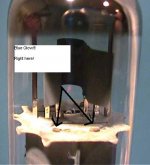
well I flicked the switch, and saw blue glow where indicated in the picture on both power tubes, there was no arching, and no sound coming out of the speaker (the volume was turned al the way down).
I saw this, and got the crap scared out of me and turned the amp off after about 5 seconds, I didn't dare turn up the volume in that time
is this in anyway, shape or form, normal?
I let the amp heat-up in standby move for a good minute while I took a picture of the amp, I flicked the switch to let the B+ into the amplifier, and I heard a pop through the speakers it wasnt a bad sounding pop, but it was rather loud, although I think it was the same pop I hear everytime I turn it off standby, even when the amp was triode-strapped.
well I flicked the switch, and saw blue glow where indicated in the picture on both power tubes, there was no arching, and no sound coming out of the speaker (the volume was turned al the way down).
I saw this, and got the crap scared out of me and turned the amp off after about 5 seconds, I didn't dare turn up the volume in that time
is this in anyway, shape or form, normal?
Attachments
I assume that you DID the usual measures when converting an amp from triode to pentode mode:
I can't understand from your picture if the glow was near the screen grid (bad) or near the glass (normal).
- re-set the bias, pentode mode will draw higher current
- protect the screen grid with a 1k resistor
I can't understand from your picture if the glow was near the screen grid (bad) or near the glass (normal).
Every one of the new production EL-34's that I have has some blue glow inside them. The JJ's (I have tried 4) have a blue glow on the inside of the plate that is visible through the holes in the plate. I am running them near (but not over) the dissipation limit. The glow is present in triode, UL and pentode mode. If I run the amp at full volume the glow dances to the music. The Shuguang tubes also glow, but it is not as obvious. Two of the Svetlanas have a relatively bright blue glow, the third also has an orange glow from some of the grid wires (bad) and the fourth has both the blue glow, and the orange glow, and it randomly arcs (real bad).
I have an old pair of Mullards, that have no visible blue in them in the same amp.
I have an old pair of Mullards, that have no visible blue in them in the same amp.
Giaime said:I assume that you DID the usual measures when converting an amp from triode to pentode mode:
- re-set the bias, pentode mode will draw higher current
- protect the screen grid with a 1k resistor
I can't understand from your picture if the glow was near the screen grid (bad) or near the glass (normal).
It was near the screen grid....
I am pretty sure my bias was set for pentode mode, but I will double check
I didn't protect the screen gird... uh oh!
what exactly do i do? put a 1k resistor between the B+ and the grid?
what exactly do i do? put a 1k resistor between the B+ and the grid?
YES. The original Mullard literature states that 1K ohms in series with the screen grid gives the lowest distortion in Ultralinear mode. I found that I like the sound better with a lower value, like 330 ohms. I have the resistor mounted right at the socket pins. It is in the circuit in all 3 modes.
Hi ghpicard,
regarding the screen resistor in UL mode:
Nope. Just apply Ohms law to your statement in the context of the the circuit and you will see that your statement is wrong.
Except, you mis-use an intentionally Pd-underated resistor as some sort of fuse")
Tom
regarding the screen resistor in UL mode:
ghpicard said:It limits screen grid current to keep screen grid dissipation within the maximum limits.
Nope. Just apply Ohms law to your statement in the context of the the circuit and you will see that your statement is wrong.
Except, you mis-use an intentionally Pd-underated resistor as some sort of fuse
Tom
Tubes4e4 said:Hi ghpicard,
regarding the screen resistor in UL mode:
Nope. Just apply Ohms law to your statement in the context of the the circuit and you will see that your statement is wrong.
Except, you mis-use an intentionally Pd-underated resistor as some sort of fuse
Tom
W=IV
V=IR
any drop in V will be made up in more I, right?
Tubes4e4 said:Hi ghpicard,
regarding the screen resistor in UL mode:
Nope. Just apply Ohms law to your statement in the context of the the circuit and you will see that your statement is wrong.
Except, you mis-use an intentionally Pd-underated resistor as some sort of fuse
Tom
Hi Tom,
Screen grid absorbs current. It has characteristic curves like the plate ones, but a function of the signal grid voltage and screen voltage.
In fact, the recommended method to set screen voltage according to RDH4 is to use a single resistor, besides the bypass capacitor to cathode.
If we don't put a resistor in the screen circuit for certain tubes (EL34 one of the usual suspects), we get that the grid current and so the dissipated screen power, without any limitation, could be higher than the rated maximum, which depends on the screen grid mechanical construction characteristics.
Then we get "glowing" screen grids and if lucky, don't lose an OPT...
We can suppose that the DC resistance of the OPT is enough to limit the value of the current to a safe limit but it would depend on the tube make, the transformer and other factors that can be easily avoided with the simple addition of a humble resistor.
IIRC, EL84 doesn't show this kind of behavoir.
And no, I like fuses to fuse and resistors to just heat
Gastón
The screen resistor is usually not large enough to cause significant voltage drop. At 20 Ma (a lot for an EL-34) you will drop 20 volts with a 1K resistor. This will lower the tube current a little, which can be made up by lowering the bias voltage a little.
The reason for the resistor is twofold. It helps prevent parasitic oscillation, especially the nasty kind that only appears near zero crossing for a few milliseconds. The second reason is that it provides a type of built in feedback that will help linearize some tubes. The EL-34 is one of these types. The resistor does little for the 6L6 family, but causes no harm.
I have learned from experience not to use the little 1/2 watt metal film resistors here, they put out a little puff of smoke, some ugly sound, then that channel goes silent. Use a 1 watt or larger resistor.
As for the cathode resistor there two ways to do this. The "proper" way is to figure out what current you want to run the tube at, and what voltage is across the tube. Then use the plate curves in the tube data to find out what bias voltage is required. Use this voltage, and the tube current to calculate the resistor. This works great if your tubes actually match the data.
Then there is "my" way. I got the "5 watt resistor kit" from DigiKey. It has a few of each of the popular flavors of 5 watt resistors. I take a guess at the value (based on the calculation above, or some other design that uses similar parameters) and install that resistor. It is best to guess on the high side. I then hook the amp up to a dummy load (a 30 watt, 8 ohm resistor that I got at Radio Shack), and the FFT analyzer (cheap, or free software and a GOOD sound card). Power up the amp and check the tube current. Try different resistor values to arrive at the desired tube current.
I run distortion and harmonic spectrum tests at full power for each of these tests. It is often the case that the best performance occurs at tube currents that result in excessive tube dissipation. A compromize must be made. The impedance of the output transformer will affect these tests. There is a different optimum point for EACH different OPT (even different transformers of the SAME impedance). I have spent the last month (and a lot of money) testing to find the optimum combination of tubes, transformers and operating conditions for my latest amp. Some of this data has been presented on this forum, and all of it will be on the web site when I am done.
Are you running EL-34's in SE? If so you may find that you will want a bit more current. I run mine at about 66 mA. Most P-P amps will want more than 25 mA per tube. Yes, you would set the LM317 to 25 (or whatever you decide on) mA. This brings me to the second problem.
Some LM317's have a maximum voltage rating of 35 volts. Some are rated to 40 volts. National Semiconductor makes an LM317HV that is good to 60 volts. Try to find these. At 66 mA my EL-34's have 37 volts on the cathodes. This is enough to zap many LM317's back into useless sand. SS devices are not like tubes where you can ignore ratings in exchange for shorter tube life, they just blow up. When they blow, they often short out. This causes the EL-34 to get real unhappy (no bias).
The cathode voltage for a certain tube current are a function of the plate curves. If I look at the tube curves on the Mullard data sheet for the EL-34, I get 32 volts (bias, or grid voltage) for 66mA and 420 plate volts. The fact that I measure 37 just shows that most current production tubes don't match 50 year old data sheets. I am using the triode curves since the static conditions for triode, UL, and pentode connections are the same unless the OPT has significant DC resistance. This assumes that G2 is tied to B+ in pentode mode.
yes, this is an SE amplifier, the tubes have a printed "Bias Point" of 25ma, but people have told me many different things, and gotten me very confused about bias current. The place where i bought the tubes (Tubedepot.com) said that the bias current is the "bias point" value listed, however I have heard many people say that it is the plate current plus the grid current.
If i put a ~4 volt LED(I have no Zeners on hand) in series with the 317, it should help eat up some of the spare voltage to take some stress off.
The 317s I bought are from ON Semiconductor (which produce the best 317s available) and are rated at 40v.
Even with JJ El34s (what I am using) do you use 66ma?
Should I change the bias current from Triode to Pentode mode?
As I explained earlier the optimum bias current for each amplifier depends on the circuit, the output transformer, your personal tastes, your choice of music (loud rock wants more juice), and even your speakers (because they are not really 8 ohms and the impedance changes with frequency).
Now that I have added some more confusion, I will attempt to clear some of it up.
The 25 mA number is printed on the box, or on a sticker, or piece of paper that came with the tubes, or on that Tube Depot label? If so this is the current that the tube drew during Tube Depots testing. Tube sellers like the Tube Depot charge a premium price for their tubes, but they pre test the tubes, and offer matched pairs. I bought mine for less money, but the JJ's came with no testing, and no current numbers. I got some Valve Art EL-34's at the same time and they were marked (probably in China), but the current varied from 21 to 44 mA. All worked fine in the amp, but each drew a slightly different current in the amp (varied from 59 to 69 mA).
In SE application you set the bias current to the value that you choose based on sound quality and expected tube life. The 25 mA number has no bearing on your choice. Yes, I run the JJ's at 66 mA in my amp, but you may want more, or less depending on your circumstances. In most SE amplifiers the power output capability increases as you increase the bias current. The distortion will also decrease to a point, and then begin to climb. Both of these are usually limited by the tubes maximum ratings.
Every tube has a maximum dissipation rating. Unfortunately these ratings are not published for most new production tubes. We must rely on 50 year old data sheets. Since Mullard invented the EL-34, I will refer to their data. In triode mode, the maximum (plate and screen grid together) dissipation is 30 watts. In pentode mode they spec the plate at 25 watts, and the screen grid at 8 watts seperately. In my testing with the JJ's (and others), I have found that the screen grid draws enough current to dissipate about 3 watts even when pounded hard at 430 volts, so we are limited by the plates 25 watts. This gives us a total maximum dissipation of 30 watts in triode mode, and 28 to 30 watts in pentode mode.
This is the "maximum" intended "design center" ratings published by Mullard in 1960. Running the tube at its maximum ratings, will usually shorten its life. By how much? We don't know. It has been stated that tubes in SE mode should be operated at 80% of the maximum, Some even say 70%. What is the maximum for new production tubes, for which there is either no published data, or obvious copies of the old Mullard data? Again, we don't know. I torture tested a few different new tubes and found that the "Winged C" (formerly Svetlana) showed signs of distress (glowing grid wires) at 30 watts. The JJ's and Valve Art EL-34's showed no signs of distress at 35 watts. I decided to run mine at 28 watts, which is close to the max. How much will this shorten their life? Only time will tell. You may want to choose a lower operating power, say 25 watts.
How do you turn this into a tube current? Well you need to know the voltage actually seen by the tube. The easiest way is to take some measurements on your amp. Other than that, you can estimate it. You need to know a few things. First obviously you need the B+ voltage. Mine is either 450 or 475 volts (I have a SS or tube rectifier switch). Then you need the cathode voltage. This will obviously change with the tube current, so you make a guess. In my case it runs from 33 to 37 volts depending on which tubes I use, and the B+ voltage. Next you need to know how much voltage is lost in the output transformer due to its DC resistance. I have been swapping transformers, so it varies a lot. I lose 13 volts in the $18 Edcors, and I lose 30 volts in the Hammond 1628SE. Subtract the cathode voltage, and the OPT loss from the B+ to get the tube voltage. I get from 383 to 425 volts. Divide the power dissipation by the tube voltage to find the tube current. Adjust the cathode resistor to get this current. The worst case for my amplifier is 28 watts divided by 425 volts to get 66 mA. I get there with a 560 ohm resistor. With the lossy transformers or the tube rectifier the tube runs well below the maximum ratings.
I use this 560 ohm resistor in triode, UL, and pentode mode. The actual current will change a little due to the fact that the screen voltage changes because of the OPT resistance (not in the circuit in pentode, partially there in UL and all there in triode). This is not an issue with a CCS. Just set it to the desired current.
You said before that you had 430 volts B+. Your cathode voltage would be around 30 volts. With a good transformer you will lose at least 10 volts. That puts your tube at 390 volts or less. If you decide on 25 watts, you can run 64 mA. 60 mA will be 23.4 watts.
As for the 4 volt LED, it would work IF it could handle the 60 (or more) mA with some safety margin. I would get everything working with a resistor (or combination of resistors) first, and then experiment with the CCS. An LM317 would still require a bypass capacitor. I am quickly becomming a fan of cathode feedback for SE amps like this. I don't know how this will work with a CCS.
Sorry for the long answer, but I find that the better I answer these questions here, the less I will be asked the same question in an e-mail to Tubelab.
Note: Do not push rare or expensive tubes this hard. limit them to the 80% or 70% rule.
- Status
- This old topic is closed. If you want to reopen this topic, contact a moderator using the "Report Post" button.
- Home
- Amplifiers
- Tubes / Valves
- Who said it was a good idea to try pentode!