I was just rumaging around in one of the old moldy stacks at the university library here recently when I came across a very aged looking old book on tube circuits.
Title: Schematico de Diophantis
After paging thru the crumbling yellow pages I came across something scribbled in a page margin:
"Cuius rei schematico mirabilem sane detexi. Hanc marginis exiguitas non caperet." signed "Pierre de F..."(unintelligible scribble)
Nothing else showed up in the margins, but inside the crumbling back cover some schematics were penciled in and signed: "Norman"
I fortunately copied these schematics down, as on my next visit to the library I only found a pile of paper crumbs on the shelf and floor. The book had disintegrated completely.
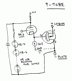
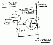
Here are the schematics I saved from the back cover (attached):
Don
Attachments
http://en.wikipedia.org/wiki/Fermat's_last_theorem
http://en.wikipedia.org/wiki/Fermat's_last_theorem
Pierre was ahead of his time, notice the holographic will he made in 1660.
Don

http://en.wikipedia.org/wiki/Fermat's_last_theorem
Pierre was ahead of his time, notice the holographic will he made in 1660.
Don
I recently talked to my cousin, recent PhD in nanophysics, about the patentsystem. One thing he said to me was that the patent of the mosfet never gave the inventor any money, because when it was finally possible to actually build them, the patent had already expired. So, the theory of the mosfet was known long before his commercial production - but I don't know exactly how long...
Erik
Erik
W. Shockley, "A Unipolar 'Field-Effect' Transistor", I.R.E. Proc., 40 (1952) pp. 1365-1376
P. K. Weimer, "The TFT - A New Thin Film Transistor", Proc. IRE, vol 50, pp. 1462-1469
P. K. Weimer, "The Insulated-Gate Thin-Film Transistor", pp147-192 in "Physics of Thin Films", vol. 2, Academic Press Inc., New York, 1963
note:
Pierre F. was famous for positing problems that could not be solved for hundreds of years.
Norman ... somebody.. solved it more recently.
OK..., it was just a joke!
Don
schematico mirabilem
about "Fermat's" last schematics:
These schematics use "inverse triode feedback" around a MosFet in order to emulate the triode's characteristics. Due to the Mosfets high input impedance and similar behavior to a tube, they are good emulations. The devices behave just like triodes, having a Mu nearly equal to the triode used in the feedback. The transconductance or Gm is that of the MosFet, so is very large. The plate resistance is derived from the usual Mu = Gm * Rp , but using the MosFet Gm here, so Rp is VERY low (suitable for direct speaker drive if using a big MosFet). Practical implementations will require a 12V or so Zener diode across the MosFet gate to source terminals for gate protective purposes. Also some form of gate "stopper" resistor or ferrite bead to prevent parasitics.
The CCS determines the tube class A operating current, grid biasing and external load will then determine voltage across the overall devices. Provision is made to separately adjust the tube operating voltage vis a vis the MosFet operating voltage so each can operate in an optimum range for the application at hand.
For the N-triode this is done via the "optional B+ boost" which can be a floating power supply as shown or a string of zeners (or NE-2 s etc) to a higher voltage supply as shown for the P-triode schematic. Similarly for the P-triode, except the voltage add-on is mandatory here since it is spanning from the MosFet negative "plate" voltage to the triode positive plate voltage. (it is providing the plate feedback path)
The separate voltage operating points are convenient for use of the P-triode and N-triode as OTL output components (for Hybrid designs) where the MosFet(s) can then use lower rail voltages suitable for the speaker drive. The boost voltages for the triodes then keeping them in a linear operating region when the MosFet voltages swing down to near zero volt differences at the output rail voltages.
Normally I would think of these as being operated in class A across the MosFets also, but nothing prohibits class AB here for P-P say except biasing stability for stable crossover characteristics.
The use of the same type of triode for both the N-triode and P-triode (along with simialr N and P channel MosFets) gives the unusual prospect of very similar characteristics for both P and N devices. Also, note that the triode turns on when the MosFet turns off for the P-triode. This is opposite to the usual SS P channel devices. This means that if you make a totem pole P-P output, the triode characteristics of the two devices will not cancel even harmonics, but will add instead. (not true for typical dual N-triode P-P into a center tapped xfmr however).
Fermat would no doubt be quite pleased with the sound! No need to use just SS sounding devices in Hybrids anymore.
Don
- Status
- This old topic is closed. If you want to reopen this topic, contact a moderator using the "Report Post" button.
- Home
- Amplifiers
- Tubes / Valves
- Positronic Tubes

