Hi all. I have some new matched 6V6GT's and some verry nice Marconi 6SJ7. I need a simple and easy to build SE schematic. I'v found this schematic :
http://www.bonavolta.ch/hobby/en/audio/6v6_5.htm
but this cathode follower doesn't look very nice to me.
Besides, I was advised not to use it
If anyone could be of assistance???
Regards
http://www.bonavolta.ch/hobby/en/audio/6v6_5.htm
but this cathode follower doesn't look very nice to me.
Besides, I was advised not to use it
If anyone could be of assistance???
Regards
Hi,
6SJ7 and 6V6 SE, eh?
Have a look at my site, you will find the most extensive and best documented circuit walkthrough available for exactly this tube combo on the whole `net, I guess. When printed out, about 25 pages on the circuit design alone
Click here for the start.
Tom
6SJ7 and 6V6 SE, eh?
Have a look at my site, you will find the most extensive and best documented circuit walkthrough available for exactly this tube combo on the whole `net, I guess. When printed out, about 25 pages on the circuit design alone
Click here for the start.
Tom
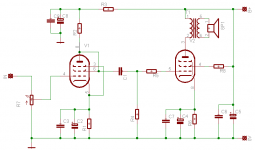
rdf said:Not to threadjack but how could the Bonavolta circuit possibly work as a generic circuit? The 6V6's bias is set by the DC resistance of the output transformer and would vary widly between models. Could this circuit have been intended for a specific transformer?
The point about varying bias is well made. Also, notice that the 6V6 is operating in triode, not pentode, mode. A triode wired 6V6 is VERY linear.
The general thrust of that 1949 circuit is valid. The 6SJ7 provides all necessary voltage gain and the 6V6 cathode follower is easy for the 6SJ7 to drive. IMO, it could be tweaked into a CAPABLE performer. Make the PSU bipolar, as that will take care of the voltage swing at the 6V6's grid. Insert a pot. between the O/P trafo and B-. Do not directly ground the O/P trafo. Adjust the pot. to set the 6V6 Ib at 35 mA. There is a flaw in the voltage gain block. The 500 nF. cap. should connect the 6SJ7's screen grid to the cathode, not ground. The ground connection would be valid if the cathode resistor was bypassed. However, yet more linear performance could be obtained by regulating the 6SJ7's screen supply. Either a VR75 or a string of low noise Zener diodes seems reasonable.
Hi Simonov,
No, because it wouldn´t make any sense at all. After all, one major point of that walkthrough was to design a pentode/pentode SE amp with gNFB.
Citing myself:
"It is a 4,5 Watt/channel pentode/pentode single ended amp which gives a damn on all this "single ended triode without any negative feedback" madness.
Instead, it is a no-fuss, well-engineered and solid circuit amp."
Tom
Did you try the schematic without NFB?
No, because it wouldn´t make any sense at all. After all, one major point of that walkthrough was to design a pentode/pentode SE amp with gNFB.
Citing myself:
"It is a 4,5 Watt/channel pentode/pentode single ended amp which gives a damn on all this "single ended triode without any negative feedback" madness.
Instead, it is a no-fuss, well-engineered and solid circuit amp."
Tom
Hi,
IMHO, the main drawback of the Bates's design is that the 6V6 is triode strapped.
By far, not the best tetrode to do that, very low current available at lo anode voltage.
Clamping screen to its cathode would probably give better results cos the 6V6 will be run in tetrode, but this calls for a choke to supply the screen and a cap to clamp it at the cathode (among other possibilities).
And a cathode follower IS a LARGELY feedbacked topology
Yves.
Yvesm said:Hi,
IMHO, the main drawback of the Bates's design is that the 6V6 is triode strapped.
By far, not the best tetrode to do that, very low current available at lo anode voltage.
Clamping screen to its cathode would probably give better results cos the 6V6 will be run in tetrode, but this calls for a choke to supply the screen and a cap to clamp it at the cathode (among other possibilities).
And a cathode follower IS a LARGELY feedbacked topology
Yves.
Both "Poindexter" and I think the 6V6 and its "equivalents" make FINE triodes. Look at the curves. They are GORGEOUS. Poinz's "Machine" and "El Cheapo" are good amps.
Yes, a cathode follower is a feedback circuit. 100% of the voltage gain is fed back LOCALLY (inside the tube). The 1949 grounded plate circuit puts the same sort of load on the "final" that the more commonly seen grounded cathode does. That goes a LONG way towards eliminating sonic flaws.
edit: fixed typos
simonov said:I was thinking about triode operatin mode for both the tubes and OPT linked in the plate circuit.
IMO, you should save the 'SJ7s for a situation that requires a lot of voltage gain. If an all triode, common cathode everywhere, circuit is what you will build, the 5965 or similar high gm/low Rp, mu in the 40s, tube will do NICELY in the voltage gain position.
I'm as big an SE fan as any but consider ditching the circuit. PSUD2 suggests ~ 340 VDC B+ with that supply given 120 ohm DCR each for choke and PS TX and a 55 ma total draw! Any reasonable estimate of OPT DCR for a modern 5K transformer is in the 250-300 ohm range. That can't be enough to prevent the tube from roasting with that B+. Assuming a lowered B+, again by any reasonable estimate of the 6V6 standing bias current there couldn't be more 10-15 VDC from cathode to grid. In a cathode follower doesn't that translate to a maximum cathode, and therefore maximum primary, swing of 20-30 volt p-p? What's the maximum output voltage of this circuit, under a 1/4 watt? Is my math-fu out?
Edit: I still wonder if this was designed with a specific model of transformer in mind.
Edit: I still wonder if this was designed with a specific model of transformer in mind.
rdf said:Edit: I still wonder if this was designed with a specific model of transformer in mind.
Bates amplifier would certainty have to by made with custom OPT. Finding suitable transformer is almost impossible.

AndreasS said:I've build the Bates-amplifier with the Hammond 124BSE (R = 240 Ohm), the sreen grid of the 6V6 on 180 Volt.
Best regards
Andreas
How does it sound?
simonov said:How does it sound?
Good. But i build this as a line amplifier (Z out < 30 ohm).
regards Andreas
- Status
- This old topic is closed. If you want to reopen this topic, contact a moderator using the "Report Post" button.
- Home
- Amplifiers
- Tubes / Valves
- 6V6GT SE schematic -need!!!