This is a pentode mode PP amp. I don't have a UL OPT, so it's either pentode or triode mode for me. I already have a triode mode amp and it works just fine. However, I'm itching to try pentode!
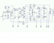
I used this particular design because I wanted to apply fairly heavy local feedback, from the OP Tube plates to the driver cathodes. I found this worked better if the drivers were separate from the phase splitter, which ruled out the Mullard approach and left me with the concertina splitter (as in the Williamson). To minimise LF instability, I put in step-network coupling between the drivers and OP tubes.
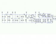
The PS uses a hybrid SS and vacuum tube Graetz bridge rectifier. There is a C-L-C filter with 5H choke in the negative line, which feeds the OPT center-taps. The screen supply uses active regulation with a couple of MOSFETs. The negative B- supply uses passive regulation with a MOSFET.
I haven't built this amp yet but it looks OK modeled with LTSpice. One channel of the amp is shown in attachment below and the PS schematic, to serve both channels, is attached to the next post.
I would be grateful for your criticism of this amp design, for or against, before I build it. Thanks in advance!
I used this particular design because I wanted to apply fairly heavy local feedback, from the OP Tube plates to the driver cathodes. I found this worked better if the drivers were separate from the phase splitter, which ruled out the Mullard approach and left me with the concertina splitter (as in the Williamson). To minimise LF instability, I put in step-network coupling between the drivers and OP tubes.
The PS uses a hybrid SS and vacuum tube Graetz bridge rectifier. There is a C-L-C filter with 5H choke in the negative line, which feeds the OPT center-taps. The screen supply uses active regulation with a couple of MOSFETs. The negative B- supply uses passive regulation with a MOSFET.
I haven't built this amp yet but it looks OK modeled with LTSpice. One channel of the amp is shown in attachment below and the PS schematic, to serve both channels, is attached to the next post.
I would be grateful for your criticism of this amp design, for or against, before I build it. Thanks in advance!
Attachments
SY said:As long as you've got them, you might think about using 6L6 types instead of EL34 and run AB2.
Why? I haven't used 6L6 much. Are they better for grid current than EL34? More linear, less current, what?
SY said:I haven't used 6AU6 triode-connected. How linear are they?
An article from Radiotronics about doing just that, with curves.
Scroll down a bit, I can create PDF's, but not edit them...
link
Thanks for that. The split load has something less than unity gain (and lots of degeneration), so the burden is placed on that first tube. I'd be interested in any actual distortion measurements on trioded 6AU6- I've got some, but can't seem to get the time to jig them up and measure it myself.
Thanks for the comments!
The first 6AU6 is a voltage amplifier in pentode mode. I thought of using EF86 (and in the end I still might do so) but, since I have some 6AU6s and they seem to have found favour in a few audio designs (Gary Pimm likes them, for example), I thought I may as well try them first. I'll use a well-behaved RCA 6AU6 for this voltage amp stage and a rather more microphonic GE 6AU6 that I have for the next stage.
The second 6AU6, in triode mode, is a convenient way for me to provide a single triode, with a small footprint, to act as the concertina splitter. The 6AU6 is quite linear used like this, it has lowish plate resistance of ~7.5k and likes a reasonably high current, so it seems a good candidate as a concertina splitter.
I'm trying to create an amp here that shows pentodes up in their best possible light. The cathode followers are in there, as SY said, to avoid blocking distortion and to give a bit more headroom, with more polite behaviour in the event of overload. I could omit the cfs, of course, without making any major changes elsewhere in the circuit but I've got the tubes to do it, so why not use them?
I'll take your word for it that EL34s don't give much extra power in class AB2 (pentodes usually don't, as I understand it). However, EL34 is the type of tubes I have and I didn't intend to use Class AB2, anyway, except for where it may occur through transients. I accept that beam tetrodes such as 6L6 can give worthwhile extra power in AB2 but the problem is that I don't own any 6L6s. My OPTs (3.5k p-p) wouldn't suit them anyway.
Okay, Okay! 6L6 is better, and 807 is better still, especially if you want class AB2. However, I am not in a position to change from EL34.
Admittedly, petode mode (or beam tetrode mode) does give you absolute felxibility regarding screen grid voltage, so all sorts of possibilities arise - even a pair of 6146s for a cool 100 watts (although I've read they'rs not very stable).
Anyway, what I was hoping for was some criticism of the circuit design. How about the NFB loops, for instance? Make sense? The step networks between the 6SN7 PP amp and the 6SN7 cf drivers? (Sorry, I erroneously said between drivers and OP tubes earlier.)
I realise the little anti-ringing and anti-HF instability networks - across stage1 plate load, local loop FB resistors and global loop FB resistor - are bound to need tweaking, once the thing is built. It's hard to allow for real life stray capacitance and leakage inductance in LTSpice.
Are the step networks actually necessary? It looks like you've got a dominant LF rolloff set by the first RC networks which is some 15 times higher than the next rolloff. I'd think that would be stable, though I haven't plotted a Bode.
What do the 330k resistors in the 6SN7 drivers do?
What do the 330k resistors in the 6SN7 drivers do?
Yes, it probably would be stable without the step network, according to LTSpice anyway (I'm waiting for somebody to make the point that you can go only so far with simulation, then you have to face the real world!).
Perhaps the step network is a bit of "belt-and-braces", to avoid being on the brink of instability. I always like to criticize the Williamson design for that, whenever I get the chance, so it would be inconsistent of me not to (over) compensate!
The step network changes the way fixed bias has to be applied, of course, and I think the bias control could be a bit too sensitive. I'll probably have to think up some sort of vernier arrangement, with "coarse" and "fine" controls, for the bias voltage setting.
They help to achieve a suitable bias point for the drivers, so that plate current is reasonable despite the direct coupling of the FB loops between the plates of the EL34s and the driver cathodes. I wanted to avoid having to use capacitors in series with the NFB resistors (the other way of arranging it).What do the 330k resistors in the 6SN7 drivers do?
A consequence of doing without a NFB coupling cap is that there will be a big voltage drop and lot of heat dissipation in the NFB loop. For this reason, I intend using two resistors in series, as shown, in each half of the FB loop. This will share the voltage drop and the heat dissipation between the two resistors.
- Status
- This old topic is closed. If you want to reopen this topic, contact a moderator using the "Report Post" button.
- Home
- Amplifiers
- Tubes / Valves
- Pentode PP amp for comments, please