Hi Friends.
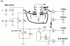
How I can make a subtract amplifier with tubes? I'm talking to a friend to make a surround sound decoder from stereo. But I'm not like to do this with op-amps. I like to do with tubes.
I haven't idea to how make this. But I think I need a negative input and a postive input.
I'm not talking about pre-amplifier, amplifiers or anymore. I'm talking to all to make a surround decoder for stereo sound!
In OP-AMPS this is very simple:
Page: http://sound.westhost.com/project18.htm
But, the problem to make it with tubes is HOW I MAKE A SUBTRACT AMPLIFIER WITH TUBES?
This is the frist problem...
Best Regards,
Felipe Navarro
How I can make a subtract amplifier with tubes? I'm talking to a friend to make a surround sound decoder from stereo. But I'm not like to do this with op-amps. I like to do with tubes.
I haven't idea to how make this. But I think I need a negative input and a postive input.
I'm not talking about pre-amplifier, amplifiers or anymore. I'm talking to all to make a surround decoder for stereo sound!
In OP-AMPS this is very simple:
An externally hosted image should be here but it was not working when we last tested it.
Page: http://sound.westhost.com/project18.htm
But, the problem to make it with tubes is HOW I MAKE A SUBTRACT AMPLIFIER WITH TUBES?
This is the frist problem...
Best Regards,
Felipe Navarro
Felipe,
Opamps were made with tubes before they were made with SS. The key element for building an opamp is the differential gain block at its I/P. The long tailed pair and Schmitt phase splitter circuits are variations on the differential amp theme. Look here.
Differential amps work best when a current sink is in the "tail". We used FETs for the CCS in "El Cheapo", but a pentode, like the 6AU6, is fine.
The 5965 is very linear and has good section to section balance. With its mu of 44, it also provides a fair amount of gain. IMO, 5965 based differential gain blocks are a good place to start your surround sound project.
Eli,
Thanks for your reply.
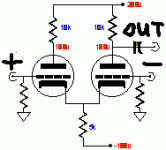
With phase splinters or diferencial amplifiers only will amplifier the sound.
I need a subtract amplifier.
I'm stay reading this page: http://www.tubecad.com/march2000/page13.html and I think i need something similiar.
The subtract amplifier diminish the differeces of the channels and make the surround sound.
Are you undestanding me?
Best Regards,
Felipe Navarro
Thanks for your reply.
With phase splinters or diferencial amplifiers only will amplifier the sound.
I need a subtract amplifier.
I'm stay reading this page: http://www.tubecad.com/march2000/page13.html and I think i need something similiar.
The subtract amplifier diminish the differeces of the channels and make the surround sound.
Are you undestanding me?
Best Regards,
Felipe Navarro
Felipe,
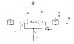
When used as a phase splitter, the non-inverting I/P is either grounded or used for the application of NFB. For your surround project, you connect a channel to the inverting I/P and the 2nd channel to the non-inverting I/P. 2 out of phase signals are produced. Those signals are the difference between the 2 channels and that's exactly what you are looking for.
Edit: typos fixed
Great idea! Muito bem!
However, I am not much of a fan of 5.1. I have heard an alternative to typical SS, known as ambiophonics (google search and you'll find a website named as such and tons of info) which in my mind sounded the most realistic that I have ever heard from non-live playback. A friend of mine modded a JVC pre DD SS decoder to do this type of SS, but he still has it.
Then there is the SpreadSpectrum version of taking stereo to trinaural. I think that could be done like this as well. Anyway, good luck with your project and keep us up on the progress.
Josh
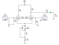
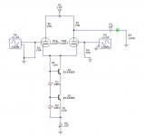
Poobah,
This is can be a CCS with LM137? I will simulate it.
Joshk,
I think my musics will be good with 4.1 ( one center chanel, one surround channel, two stereo )
I have solucioned the problem with the V5... This need to be rounded on the phase.")
Best Regards for all friends.
This is can be a CCS with LM137? I will simulate it.
Joshk,
I think my musics will be good with 4.1 ( one center chanel, one surround channel, two stereo )
I have solucioned the problem with the V5... This need to be rounded on the phase.
Best Regards for all friends.
This is the topic who are you speaking? http://www.diyaudio.com/forums/showthread.php?s=&threadid=72740
I will simulate it.
Best Regards,
Felipe Navarro
I will simulate it.
Best Regards,
Felipe Navarro
Felipe,
The resistor R1 should be connected to the posistive rail of the circuit... NOT the cathodes of the tubes. Only the collector terminal of the upper transistor behaves like a current source. You should calculate the value of the resistor to give about 5 mA thought the LED's.
Also, your B+ should be much higher... perhaps 100 - 150 volts.
- Status
- This old topic is closed. If you want to reopen this topic, contact a moderator using the "Report Post" button.
- Home
- Amplifiers
- Tubes / Valves
- Surround Decoder - Subtract amplifier