Hi there all,
I know that this is an old topic but I want a bit of clarification before I make a final decision.
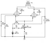
You may or may not have followed my thread about a 2 tube 6080 PP amp. I ended up with ECL82's driving a toroidal phase splitter and finally 6080's in a push pull configuration. I used seperate bypassed 330R resistor, with a parallel 2K in series with a 1K5 pot, to give me bias adjustment.That is each triode has it own bypassed cathode resistor. This works really well and sound good with excellent bass as is. I am sufficiently impressed that i think with a bit of tweaking it will sound much better than my set amp.
However I am concerned about bias drift over time, so I was thinking about various methods of automatic bias adjustment. I originally thought about using the "garter circuit" as mentioned in Tubecad, but I didn't have enough spare voltage and it required the insertion of another cap in the output grids.
After reading about a differential output stage in a "Vacuum State" power amp, I am now think about individual Constant Current sinks in each cathode. Again the inspiration has come from Tubecad. I was thinking of using simple bypassed LM317 CCS. Since the 6080 is biased at 30V the use of LM317's is a bit marginal so I was going to put a NPN transistor in series with it. The bias point of the transistor would be set with a resistor network at about 10V. This should let the transistor take the strain.
Is it a good idea to use seperate CCS's per triode or would I be better with just one per push pull pair ?
Are there any dangers to this approach?
Can I expect an improvement in detail and bass control ?
Thanks
Shoog
I know that this is an old topic but I want a bit of clarification before I make a final decision.
You may or may not have followed my thread about a 2 tube 6080 PP amp. I ended up with ECL82's driving a toroidal phase splitter and finally 6080's in a push pull configuration. I used seperate bypassed 330R resistor, with a parallel 2K in series with a 1K5 pot, to give me bias adjustment.That is each triode has it own bypassed cathode resistor. This works really well and sound good with excellent bass as is. I am sufficiently impressed that i think with a bit of tweaking it will sound much better than my set amp.
However I am concerned about bias drift over time, so I was thinking about various methods of automatic bias adjustment. I originally thought about using the "garter circuit" as mentioned in Tubecad, but I didn't have enough spare voltage and it required the insertion of another cap in the output grids.
After reading about a differential output stage in a "Vacuum State" power amp, I am now think about individual Constant Current sinks in each cathode. Again the inspiration has come from Tubecad. I was thinking of using simple bypassed LM317 CCS. Since the 6080 is biased at 30V the use of LM317's is a bit marginal so I was going to put a NPN transistor in series with it. The bias point of the transistor would be set with a resistor network at about 10V. This should let the transistor take the strain.
Is it a good idea to use seperate CCS's per triode or would I be better with just one per push pull pair ?
Are there any dangers to this approach?
Can I expect an improvement in detail and bass control ?
Thanks
Shoog
Hey, I am acutally struggling with the same problem right now, only I am worrying about the EL34, however you seem to know alot more about this than myself. the EL34 has a bias in upwards of 35V which is enough for an LM317HV, however I can't hanlde both EL34s on one LM317HV or the LM317.
My questions is some more basic than yours, but does anyone have any ideas as to how I can achive this? possibly with a stronger regulator?
I am so happy that you raised this question as it is directly related to my own, thank you!
My questions is some more basic than yours, but does anyone have any ideas as to how I can achive this? possibly with a stronger regulator?
I am so happy that you raised this question as it is directly related to my own, thank you!
Hi ALexmoose
As far as my common sense goes I would say that the LM317HV can handle two EL34's. With the cathodes tied together you will keep same bias voltage, just the current will double...and that is no problem for a heatsinked LM317!
And Shoog, I can't be of much help. I just know that Ian (gingertube) said he got the best bass from his baby huey by using 'bias blocks' for the EL84's. Also, DC balance in a toroid OPT seems to be a very important thing, so a way of providing constant bias would seem to be a good thing to do. Besides the traditional LM317 CCS I can only think on the 'bias blocks' used through Ian and the CCS boards from diyaudio.
erik
Interesting article can be found at
http://www.glass-ware.com/tubecircuits/Tube_Auto_Biasing.html
Seems that the raw LM317 can well handle the needed 30V of bias, so that makes the whole arrangement very simple. 4xLM317 and 4x 12R resistor, big heatsink (12 watts dissipation total).
The nice thing is that I built this amp in a very modular form. The bias arrangement is mounted on a seperate board and the cathode bypass caps are hanging of the valve bases. Therefore all I need to do is build a replacement board and switch them over. Couldn't be simpler.
Just need to get the LM317's now. I believe I have a pair stashed already.
Shoog
ErikdeBest said:Hi ALexmoose
As far as my common sense goes I would say that the LM317HV can handle two EL34's. With the cathodes tied together you will keep same bias voltage, just the current will double...and that is no problem for a heatsinked LM317!
erik
okay, that re-assures me alot, but is there anything I can do to maybe get a little bit of headroom with the bias voltage?
Hi Alexmoose
I understand your point. You can try the tricks with zeners or a mosfet, cited by broskie http://www.glass-ware.com/tubecircuits/Tube_Auto_Biasing_2.html
Or you build a bias block just like the one made by Gingertube for his baby huey. Just be sure to use transistors that handle the extra current - and heatsink them!
Erik
What do you mean by headroom alexmoose? Are you expecting a voltage swing at the cathodes?
What are the anode and screen voltages? With an EL34 the bias voltage shouldn't be so high no matter which values. If in doubt, just place a HV MOSFET on top of the CCS, give the CCS enough voltage to sink whatever current without overheating, and heatsink the MOSFET instead.
If you plan on a pure classA amp you can have a single CCS connected to both cathodes, kinda like a long tail pair, and even leave out any bypass caps. But if you want any extra juice as the tubes go past classA, you need the cap to supply the current. Since the cap is what supplies the signal current you do not need more than one CCS, but having one on each tube helps if you like to run each tube at the same current since you'd be able to adjust each seperately.
If you do end up using a MOSFET, you might as well ditch the LM chip, and just bias the MOSFET with a 6.2V zener and save some pennies.
You want better regulation too? Not that there should be any voltage swing to mess up the CCS, but putting that MOSFET on top will shield the CCS from any variations, so not only protect it from over voltage but also make for a more constant constant current source.
Honestly, this is the first project i am working on where the bias is not simply a resistor going to the ground. so I am still new to the concept of a CCS
The Bias on the El34 is going to be around 35v per tube, and the total current should be around 120ma between the two tubes I see the set-up you have, and it looks like it would work, but how would I make sure the bias voltage, and the current is correct?
The Bias on the El34 is going to be around 35v per tube, and the total current should be around 120ma between the two tubes I see the set-up you have, and it looks like it would work, but how would I make sure the bias voltage, and the current is correct?
By fixing the current through the cathode, the bias point moves to the correct bias voltage for that current automatically (its like magic).
The advantage in using one CCS per tube is that the current in the output transformer will by perfectly matched and so there will be no standing DC. This should increase the transformer performance dramatically. In my application with toroidals this is essential. For my money, this alone is worth having one CCS per tube. Never having to worry about bias drift and resetting bias points is the other.
With valves with better tolerances the last point should be less of an issue. I would say that if you use the LM317HV then they should cope with your application perfectly by themselves. Just make certain that they are well heatsinked.
I spent yesterday building my CCS replacement board. Used salvaged LM317's. Tested them and they deliver within 1mA of each other. Not quite as accurate as I had hoped, but good enough. Using chips out of the same batch should make for better matching. Will hopefully hook them up today and will be able to report back on the difference.
Shoog
Tested them and they deliver within 1mA of each other.
But 1mA is just 1% of the 100mA you are looking for. The tolerances on the 317, if I am not mistaken, is 4%, or 2%, for the better version.
Erik
Shoog said:By fixing the current through the cathode, the bias point moves to the correct bias voltage for that current automatically (its like magic).
The advantage in using one CCS per tube is that the current in the output transformer will by perfectly matched and so there will be no standing DC. This should increase the transformer performance dramatically. In my application with toroidals this is essential. For my money, this alone is worth having one CCS per tube. Never having to worry about bias drift and resetting bias points is the other.
With valves with better tolerances the last point should be less of an issue. I would say that if you use the LM317HV then they should cope with your application perfectly by themselves. Just make certain that they are well heatsinked.
Shoog
Okay, that makes alot of sense, but now I have two farily simple questions
1. do you seggest one lm317hv per push-pull pair, or one per tube? or is it a matter of opinion?
3. from my plate, dissopation, plate current, and B+ voltage, how do I determain what my bias voltage should be on an El34?
Great suggestion by Shoog. And about question 2 - I imagine you already have an amp up and running? So you should know the current through the EL34's, or you can easily measure it. So, take 1,2 and divide it through the current (in mA): this is the value for the programming resistor. Now just install this in the cathode circuit, as shown by Broskie.
Don't forget heatsink
Erik
Don't forget heatsink
Erik
- Status
- This old topic is closed. If you want to reopen this topic, contact a moderator using the "Report Post" button.
- Home
- Amplifiers
- Tubes / Valves
- CCS current sink in the output of my 2 tube 6080 amp.