After gaining some confidence in building some low voltage solid state power supplies for CD players thought I’d tackling a valve regulated power supply for a preamp.
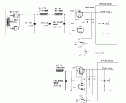
I have gleaned much information from the posts here and have adapted part of Frank’s 250V regulated power supply using a CLCLC filter prior to regulation. However, since this is my first DIY adventure into building valve stuff I thought I’d get some feedback and advice before I actually build the circuit attached.
I was going to use this power supply for an Aikido preamp (current draw approx 30mA/channel) build would also like the versatility of using it for other circuits, maybe an Ultrapath.
Transformers and chokes have been salvaged and capacitors are MKP motor run. I will be using a 5W4G valve rectifier which seems similar to the 5Y3G on paper.
Using Power supply Designer II, I’ve used C1 (0.47uF) to set the voltage to 300V prior to the regulator.
My major questions are:
By splitting the voltage into R & L channels after C2, would the added capacitance of C3a & C3b and C4 on each channel overload the rectifier ?
Although I’ve used a small input cap will it still function similar to a choke input (constant current) power supply?
It all seems overkill (but I’m using salvaged parts), would there be a loss in performance by simplifying it by something like:
270V – 0 -270V -> 5W4G -> 10uF -> 7H (88ohms) -> 100uF -> 7H (88ohms) -> 100uF, then split into R & L each with the regulator?
Any feedback and advice appreciated.
Cheers
Richard
Attachments
No. The effect would be negligible as the rectifier is hiding behind the chokes, so to speak.Richard said:By splitting the voltage into R & L channels after C2, would the added capacitance of C3a & C3b and C4 on each channel overload the rectifier ?
I feel that with that value of capacitor, it could be borderline. This is not generally a way I would choose to achieve a desired B+. The way I would choose depends on the type of amp it will power.Although I’ve used a small input cap will it still function similar to a choke input (constant current) power supply?
I think the regulators will compensate for any issues. If not for them, I would rather use separate inductors/capacitors. In fact, with the regulators, your earlier stages almost look like overkill, but that isn't badwould there be a loss in performance by simplifying it by something like:
270V – 0 -270V -> 5W4G -> 10uF -> 7H (88ohms) -> 100uF -> 7H (88ohms) -> 100uF, then split into R & L each with the regulator?
")
Hi Indm
Thank you very much for the feedback. If I could trouble you some more
Would you care to elaborate?
I have modelled using a larger cap and a RC filter to reduce B+. However, PSD II indicates that "the IFRM (current forward rectifier maximum) of 0.38A has been exceeded" when anything greater than 2uF after the rectifier is used.
Using a 270V - 0 - 270v transformer and C1 of 20uF C2 = C3 =80uF gives me the voltage I need b4 the regulator and does not exceed the IRFM, but any increase in capacitance does. And I planned to put at leat 80uf after the reg.
How could I address this issue of IRFM, while using the 5W4G rectifier?
Cheers
Rich
Thank you very much for the feedback. If I could trouble you some more
I feel that with that value of capacitor, it could be borderline. This is not generally a way I would choose to achieve a desired B+. The way I would choose depends on the type of amp it will power.
Would you care to elaborate?
I have modelled using a larger cap and a RC filter to reduce B+. However, PSD II indicates that "the IFRM (current forward rectifier maximum) of 0.38A has been exceeded" when anything greater than 2uF after the rectifier is used.
Using a 270V - 0 - 270v transformer and C1 of 20uF C2 = C3 =80uF gives me the voltage I need b4 the regulator and does not exceed the IRFM, but any increase in capacitance does. And I planned to put at leat 80uf after the reg.
How could I address this issue of IRFM, while using the 5W4G rectifier?
Cheers
Rich
OK, some points.
The spec sheet specifies a max of 4uF for capacitor input. This is a directly heated device, there is therefore no controlled warmup to hold the B+ off the other devices before they are warm. You could implement this some other way if you wanted to. Have you considered any other rectifiers?
Chokes in the power supply can account for ringing. When designed well, chokes in a power supply are a good thing. If not, and even if they don't cause a ringing problem, they can cause spikes that exceed rectifier limits at turnon.
If you are designing an amp with a relatively non constant current draw, such as with a class AB output stage, you would want a minimum of series resistances in the supply as these will drop a varying voltage with the varying current.
Similarly, using a borderline small input cap may produce a rectified voltage that is too dependent on current draw.
I'm not sure I understand when you said that 2uF was too much, then said that you tried 20uF and it was good. Could you put it another way perhaps?
I wonder whether you might find this interesting http://www.siteswithstyle.com/VoltSecond/CLC_ringing/CLC_ringing.html
it is a little about what is going on between your rectifier and regulator.
Hi Indm & others,
Thanks for feedback and the link, I did find it very useful.
I have considered other rectifiers like the 5V4/GZ32 as I have a couple but most of the ones I have are directly heated and I also managed to get the 5W4’s cheep.
The fast turn on will only effect the ECL85 in the regulator as the signal valve heaters will be supplied by a separate XF and PSU.
In regard to the link of PS ringing, a few points gathered from the website:
“As expected with large resistances, the damping is good, but the regulation is poor”
“The first capacitor after the rectifiers affects both damping and regulation. Bigger is not necessary better in this location”.
“Low DCR in the inductor is good, but it can be over done. If you buy a low DCR inductor, lower the Zo of the LC tank by buying a larger capacitor for C out.”
The aikido preamp it will be powering will be running 5-6mA per triode so 20-30mA per channel (total of approx 50 + 10mA)
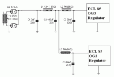
I have remodelled the PS b4 the rectifier using a 270-0-270 V transformer and a 3uF input cap. This time I have used a low DCR inductor (67 ohms). I didn’t find any differences in PSD II by increasing the inductors DCR to 167 ohms (by adding R in series), so left it at 67ohms. In light of this I have increased C2 (C out) to 100uF.
All in all the PS gives me about 270V prior to the regulator depending on current draw. By changing to a 5V4 and leaving C1 at 3uF, voltage increases to approx 290V, but seems to show a very little ringing. Replacing the 12H 67 ohm inductor with the 19H 234ohm one does cure the ringing so to does adding 200ohm series resistance to the 12H ie making 267ohms.
I will try and put together the PS this weekend, but until then any comments & suggestions are most welcome.
Cheers
Richard
Thanks for feedback and the link, I did find it very useful.
This is a directly heated device, there is therefore no controlled warmup to hold the B+ off the other devices before they are warm. You could implement this some other way if you wanted to. Have you considered any other rectifiers?
I have considered other rectifiers like the 5V4/GZ32 as I have a couple but most of the ones I have are directly heated and I also managed to get the 5W4’s cheep.
The fast turn on will only effect the ECL85 in the regulator as the signal valve heaters will be supplied by a separate XF and PSU.
In regard to the link of PS ringing, a few points gathered from the website:
“As expected with large resistances, the damping is good, but the regulation is poor”
“The first capacitor after the rectifiers affects both damping and regulation. Bigger is not necessary better in this location”.
“Low DCR in the inductor is good, but it can be over done. If you buy a low DCR inductor, lower the Zo of the LC tank by buying a larger capacitor for C out.”
Sorry my mistakeI'm not sure I understand when you said that 2uF was too much, then said that you tried 20uF and it was good. Could you put it another way perhaps?
The aikido preamp it will be powering will be running 5-6mA per triode so 20-30mA per channel (total of approx 50 + 10mA)
Is there any golden rule for minimum resistance?you would want a minimum of series resistances in the supply as these will drop a varying voltage with the varying current.
I have remodelled the PS b4 the rectifier using a 270-0-270 V transformer and a 3uF input cap. This time I have used a low DCR inductor (67 ohms). I didn’t find any differences in PSD II by increasing the inductors DCR to 167 ohms (by adding R in series), so left it at 67ohms. In light of this I have increased C2 (C out) to 100uF.
All in all the PS gives me about 270V prior to the regulator depending on current draw. By changing to a 5V4 and leaving C1 at 3uF, voltage increases to approx 290V, but seems to show a very little ringing. Replacing the 12H 67 ohm inductor with the 19H 234ohm one does cure the ringing so to does adding 200ohm series resistance to the 12H ie making 267ohms.
I will try and put together the PS this weekend, but until then any comments & suggestions are most welcome.
Cheers
Richard
Attachments
Richard said:Any feedback and advice appreciated.
Cheers
Richard
With active regulation, you don't need a CLCLC filter. Save that iron for more projects! Unless you just have to have the glowey bottles cuteness, I'd solid state the whole thing. That way, silicon diodes could work into a filter capacitor, and then use a power MOSFET for a series pass element. The higher gain, and better isolation, can provide all the ripple rejection you'll need. You could still use that VR tube, as it would probably work better than a bunch of series Zeners (high voltage Zeners drift quite a bit) and would definitely be quieter.
Increasing DCR of chokes with a series resistor
Hi Miles
Many thanks for the feedback. It’s an excellent idea of using solid state. There is a nice example of a regulated solid state power supply for preamps in Morgan Jones Valve amplifiers 3rd edition. As a novice I was considering building that, but I wanted to learn about valve PSU and just love the look of “glowey bottles” on a cold night.
After some more modelling I finally seem to have a better understand of the link Indm posted regarding ringing. I tried the following (Please forgive the repetition):
The 5Y3 was modelled instead of 5W4
270-0-270 -->5W4 -->3uF-->12H 67ohms--> 120uF --> 7H 88ohms --> 80uF
changing the rectifier to 5V4 and increase the input cap to 6uF, to get more B+
270-0-270 -->5V4 -->6uF-->12H 67ohms--> 120uF --> 7H 88ohms --> 80uF
Both designs above exhibit a little ringing
increasing the series resistance of the chokes (by adding a resistor immediately before the choke) yields a smoother V out curve, thereby curing ringing.
Ie
270-0-270 -->5V4 -->6uF-->12H 167ohms--> 120uF --> 7H 188ohms --> 80uF
Forgive my ignorance, but can anyone comment on increasing a chokes DCR by just adding a resistor in series, is it allowable ?
Richard
Re: Increasing DCR of chokes with a series resistor
Yes, it is.Richard said:can anyone comment on increasing a chokes DCR by just adding a resistor in series, is it allowable ?
Is this what you're looking for? http://www.mif.pg.gda.pl/homepages/frank/sheets/049/5/5W4.pdf
- Status
- This old topic is closed. If you want to reopen this topic, contact a moderator using the "Report Post" button.
- Home
- Amplifiers
- Tubes / Valves
- Some advice on this power supply