")
Speaking of Red-Light-District:
I did a *LED-Light-District* version, as it wasn't all Red but Red & Green ...
The outputs were smaller tubes, 6P9, which don't glow because they are all black steel.
So I thought a little LED light would make it more attractive ...
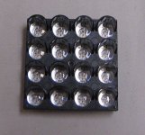
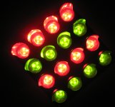
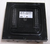
Anyway, I remembered that I had a 4x4 matrix module laying around somewhere, part of an alphanumeric display panel. Each of its 16 dots is comprised of 3 red and 3 green LEDs, 96 in total, just enough for two channels. The triplets are already series wired internally, and brought out in the rear on two dual inline rows of pins.
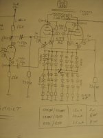
Easy wiring I thought ... and then I suddenly realised that it might be a nice feature to reconfigure the array as either (all red), (half red / half green), and (all green), which means three different bias settings (low / medium / high).
But lightning struck when I discovered that it can be done with one single on-off-on switch.
And what is more, this switch can be actuated live, on the fly, without any audible noise or plop or crackle.
It works like so:
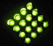
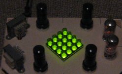
- switch in neutral: all green LEDs are on, highest voltage drop, low bias current
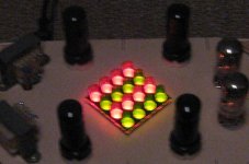
- switch up: half red / half green , medium voltage drop, medium bias current
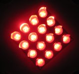
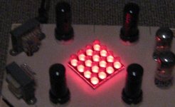
- switch down: all red LEDs are on, lowest voltage drop, high bias current.
Note: red and green in parallel means that only the red ones turn on, stealing all the current from the green ones ...
Another nice thing with this module is, that when it was manufactured most likely the LED dies (dice ?) were taken from the same wafer, so they have near identical forward voltage drop and only very small series resistors are needed, if any.
The pictures are from the prototype built on a small fruit crate, LOL, but they show the general arrangement.
The LEDs run near their max dissipation with the 6P9, more powerful tubes would probably require 2 of these modules, one per channel.
I did a *LED-Light-District* version, as it wasn't all Red but Red & Green ...
The outputs were smaller tubes, 6P9, which don't glow because they are all black steel.
So I thought a little LED light would make it more attractive ...
Anyway, I remembered that I had a 4x4 matrix module laying around somewhere, part of an alphanumeric display panel. Each of its 16 dots is comprised of 3 red and 3 green LEDs, 96 in total, just enough for two channels. The triplets are already series wired internally, and brought out in the rear on two dual inline rows of pins.
Easy wiring I thought ... and then I suddenly realised that it might be a nice feature to reconfigure the array as either (all red), (half red / half green), and (all green), which means three different bias settings (low / medium / high).
But lightning struck when I discovered that it can be done with one single on-off-on switch.
And what is more, this switch can be actuated live, on the fly, without any audible noise or plop or crackle.
It works like so:
- switch in neutral: all green LEDs are on, highest voltage drop, low bias current
- switch up: half red / half green , medium voltage drop, medium bias current
- switch down: all red LEDs are on, lowest voltage drop, high bias current.
Note: red and green in parallel means that only the red ones turn on, stealing all the current from the green ones ...
Another nice thing with this module is, that when it was manufactured most likely the LED dies (dice ?) were taken from the same wafer, so they have near identical forward voltage drop and only very small series resistors are needed, if any.
The pictures are from the prototype built on a small fruit crate, LOL, but they show the general arrangement.
The LEDs run near their max dissipation with the 6P9, more powerful tubes would probably require 2 of these modules, one per channel.
Attachments
Last edited:
Easy fellas.
The RDL sounds good. When I get the time, I may build one. So while it may not be the best amplifier you have heard, it isn't bad.` Most of the sound quality will depend on the iron you use.
I use custom Hammond transformers in my projects and they always sound better than average. All I can say is, thank you Hammond!
-Chris
After a very long run-up my Red Light District is finally making music. First of all, thanks to SY for this great project, but I also very much appreciate all the tips and tricks throughout this thread from other members.
My version uses iron from Edcor, specifically the Pete Millett set for the "Engineer's Amplifier" + an extra power transformer to have individual supplies for each channel. This gives a B+ of 360V, and I have 75mA for cathode current. For the driver supply I found a very anonymous PCB mount transformer that gave somewhat more than 400V under load, so it had to be padded down a bit. The Edcor power trafos is a bit noisy, mechanically, but nothing I can detect from the couch when music is playing. I have not yet tried running it through an isolation transformer or otherwise debugged this, but I would probably not buy them again.
Another question that has been asked many times in this thread, is what output transformers to get. The Edcors are doing fine job, but if I was to do it again I would spend more money here. SY's design deserves it!
I found a batch of hlmp-6000 LEDs and 7 strings with 6 in each works nicely. They are surface mount versions which put my patience to test....
It is constructed on a 10mm aluminium plate that went through the CNC milling machine, with the LEDs and Maida regulators on PCB and the audio circuit on a perf bord. Carrying the various bits and pieces on the underside are laser cut and bend 2mm stainless steel sheet metal. Nice and sturdy. I can recommend Neutrik RCA and SpeakOn connectors. If you get inspired by this, talk to you local machine shop; maybe they are not to unreasonable about the cost of doing a bit of metal work. PM me for CAD files.
To get all the way to the finish line I still need to do some wire dressing, a PCB for the audio circuit will be ordered and it will get wooden front and side panels to make it look pretty (and safe!).
It is doing very well as an integrated amp with an added volume control and an input selector. Right now it drives Lynn Olsons ME2 speakers. I can highly recommend it, also as a beginner project!
Jacob
- Home
- Amplifiers
- Tubes / Valves
- The Red Light District - another PP EL84 amp