got it,thanks for clarifying, i'm trying to sort this out as i had the idea of experimenting with a ccs CF driving headphones(based on a 6as7 or 6080 as the CF) what do you think of this idea? your views are appreciated. I have lot's to learn first before i either abandon the idea or pursue it!
The transistor types are the wrong way round in that diagram. The MJE350 should be nearest the valve and the BC557C furthest away.
Edited the circuit on post #31. Thanks for spotting the error.
An externally hosted image should be here but it was not working when we last tested it.
burnedfingers said:Could you use a 2N5401 in place of the BC557?
You could, but it's not very good. It has a higher Vcbo rating than is necessary in this application and that compromises the hfe. The transistor associated with the LED only needs to withstand a few volts but it needs as much hfe as possible (hfe > 400 is what you're looking for).
burnedfingers said:What is your B+ voltage you are feeding the CCS?
Hi,
I am going to use a 300Vdc supply.
SY, EC8010,
Guys, thanks a lot for the help. Direct-coupled to a cf with ccs. The sounds is so ohlala for me, here she is!
I adjusted for 8mA using the 20K to a voltage of 160V but when I inserted the tubes I measured 180V on the plates. There are no glowing plates (thank goodness ), just glowing heaters and those wonderful LEDs. The bright 5mm drops 3.5V (2 X 1.75V).
The cf ccs uses 3mm LEDs since those were I had, but will replace with 5mm ones that have higher brightness with the same current rating later on. Transistors on the plate ccs were matched with an hfe meter with the LED transistors having an hfe of 430.
I had to construct a chassis from aluminum profiles since I ran out of alligator clips.
It doesn't look much really but in the end, it's all about the sound.
Guys, thanks a lot for the help. Direct-coupled to a cf with ccs. The sounds is so ohlala for me, here she is!
An externally hosted image should be here but it was not working when we last tested it.
I adjusted for 8mA using the 20K to a voltage of 160V but when I inserted the tubes I measured 180V on the plates. There are no glowing plates (thank goodness
), just glowing heaters and those wonderful LEDs. The bright 5mm drops 3.5V (2 X 1.75V).The cf ccs uses 3mm LEDs since those were I had, but will replace with 5mm ones that have higher brightness with the same current rating later on. Transistors on the plate ccs were matched with an hfe meter with the LED transistors having an hfe of 430.
An externally hosted image should be here but it was not working when we last tested it.
I had to construct a chassis from aluminum profiles since I ran out of alligator clips.
An externally hosted image should be here but it was not working when we last tested it.
It doesn't look much really but in the end, it's all about the sound.
JojoD818 said:It doesn't look much really but in the end, it's all about the sound.
Perzackly. Incidentally, why change the LEDs? Electrically, the best LEDs to use in this circuit are old ones that don't produce much light. The newer, higher brightness LEDS tend to have a higher slope resistance, which means that they're not able to attenuate power supply noise as effectively.
Nice pictures, by the way; I think the chassis looks just fine.
Nice pictures, by the way; I think the chassis looks just fine.
Thanks! She really is a beauty under the chassis. At least for me, my wife thinks it's a mess.
The newer, higher brightness LEDS tend to have a higher slope resistance, which means that they're not able to attenuate power supply noise as effectively.
That's true, the bright ones are brand new, the relatively dull ones are my stock. If old ones are needed then I'm in luck for I have a bunch of them, though one of the plastic bags were not able to stop nature from corroding the some of the pins - a little scraping would do it I guess.
JojoD818 said:corroding the some of the pins - a little scraping would do it I guess.
No, no scraping. We have some stuff over here called "Silver dip". It's for cleaning silver jewellery. I'm guessing that your LED leads are silver plated and that they have oxidized black. "Silver dip" will fix that.
No, no scraping. We have some stuff over here called "Silver dip". It's for cleaning silver jewellery. I'm guessing that your LED leads are silver plated and that they have oxidized black. "Silver dip" will fix that.
Now why didn't I thought of that, a small bottle of that costs like a dollar in here. Hhmm, hope that also works on other electronic parts I have.
Cool tip indeed, thanks.Jojo, nice work!
Thanks, it has been a fun and fantastic project.
I now plan to fiddle with it for the next few days and learn more about it.
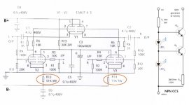
I would like to use the diyaudio CCS for my GG (schmatic attached with the CCS desing). I am thinking of putting the CCS to replace the 51K under pin 3/8 of V2 and V3 (orange circle). Read the CCS doc, referring to the examples in the doc without fully understand it (I do not have basic electronic training other than self learning) I did some calculation and put the CCS next to the GG schmatic in the attachment.
According to the GG designer, pin 3/8 should have +2.5V. So I need (200 + 2.5) / 51K = 4mA CCS. I use ground and B- (-200V) for the reference rail, so
R1 = ( 200V - 3.7V ) / 5mA = 39K, power = 5mA * (200-3.7) = 1W so I can use 3W.
R2 always has 1V drop (re. example in doc or ??), so
R2 = 1V / 4mA = 250 Ohm, power not a concern.
Q1 and Q2 can be any one suggested in the doc. LED can be any color.
Can somebody good at this advise me if my calcuation is correct?
Is there any other spot I can use CCS in the schematic?
Thanks for your help.
Attachments
If you're going to use a CCS, you don't need that very wasteful -200V supply. -12V would do perfectly well and would reduce dissipation in the CCS.
The LEDs need to be red, not modern high brightness designs, but old fashioned cheap low brightness. There has been plenty of discussion on this.
If you use -12V, you can use BC549C for both Q1 and Q2. If you have to use -200V, Q2 must be MJE340.
Your calculations are correct.
The LEDs need to be red, not modern high brightness designs, but old fashioned cheap low brightness. There has been plenty of discussion on this.
If you use -12V, you can use BC549C for both Q1 and Q2. If you have to use -200V, Q2 must be MJE340.
Your calculations are correct.
Thanks for the advise. The reason I use -200V is because there is no -12V in my GG (it has a +12V used by filament. I don't want to couple the filament ps with the amp ps). Besides, I don't know how to use a -12V here (the CCS is to replace the 51K which is between +2.5V and -200V).
CCS in GG failed
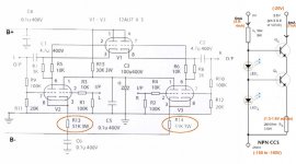
I put up a pair of CCS for my GG as in the schematic I posted last week, but it failed. I put my measurement in red below (black are the expected values). Q1 is C549B, Q2 is KSE340 (I couldn't find MJE340) with heat sink. The reference rail become 3.8-4mA instead of 5mA, the B- raised from -195V to -150 to -160V. The pin 3/8 of V2 becomes -20V instead of 2.5V and current is 7mA instead of the required 4mA. V drop across R2 is 1.3-1.6V instead of 1V. Also the 2 LED started to blink 10 sec. after power on (that's why some readings are in a range. These are the same for both channels. Can anybody point out what went wrong with my schematic?
I put up a pair of CCS for my GG as in the schematic I posted last week, but it failed. I put my measurement in red below (black are the expected values). Q1 is C549B, Q2 is KSE340 (I couldn't find MJE340) with heat sink. The reference rail become 3.8-4mA instead of 5mA, the B- raised from -195V to -150 to -160V. The pin 3/8 of V2 becomes -20V instead of 2.5V and current is 7mA instead of the required 4mA. V drop across R2 is 1.3-1.6V instead of 1V. Also the 2 LED started to blink 10 sec. after power on (that's why some readings are in a range. These are the same for both channels. Can anybody point out what went wrong with my schematic?
Attachments
- Status
- This old topic is closed. If you want to reopen this topic, contact a moderator using the "Report Post" button.
- Home
- Amplifiers
- Tubes / Valves
- Tube Amp CCS?