WOuld like to ask, on a voltage doubler on the top tube if i use a tube rectifier and the bottom rectifer i use a diode would this configuration work? Also would there be rectifer noise. This configuration looks similar to the hybrid gaertz bridge using tube and solid state diode to save a bottom tube.
THanks
THanks
A tube rectifier is a diode, therefore can be used as a diode. Some SS diodes generate noise, not because they have a low forward resistance, but because of their switch-off characteristics (e.g. stored charge).
Voltage doublers have high output resistance so are best avoided when possible. Using a tube rectifier will increase this problem.
Voltage doublers have high output resistance so are best avoided when possible. Using a tube rectifier will increase this problem.
A tube rectifier is a diode, therefore can be used as a diode. Some SS diodes generate noise, not because they have a low forward resistance, but because of their switch-off characteristics (e.g. stored charge).
Voltage doublers have high output resistance so are best avoided when possible. Using a tube rectifier will increase this problem.
Not using vacuum diodes in doubler PSUs is correct. No vacuum diode I am aware of can safely work into the huge capacitance necessary in the doubler cap. stack. However, a well executed Greinacher, AKA "full wave", doubler will have a low O/P impedance. "Morons", like McIntosh, Marantz, and Hegeman, used Greinacher doublers in some of the most revered tube amps of all time.
Today's high capacitance per unit volume electrolytics make setting up a very "stiff" stack easy. A well executed Greinacher doubler will have "gobs" of capacitance in the stack, as you have to divide by 2 to get the equivalent of FW bridges into cap. I/P filters. Everything has its price and such large caps. entail a TINY conduction angle, with a very "sharp" ripple waveform. Insert a "hash" filter made from a high current RF choke and a 10 nF. mica or NPO ceramic cap. between the doubler stack and the reservoir LC section. That way, HF noise can't sneak through the winding capacitance of the main filter choke.
BTW, a proper power trafo set up for use with a doubler can have very low copper losses. Consider the brute in the H/K Cit.2. Its rectifier winding is rated for (sic) 1.7 A.
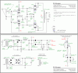
Look at the B+ supply in "El Cheapo". It's a Greinacher doubler. The ripple freq. is 2X the mains freq. Notice the LC section that forms the reservoir. The choke is important for ripple overtone suppression. The only refinement to the setup shown is to insert a LC "hash" filter section made from RF parts between the doubler stack and the main filter choke. If you want to use a cap. multiplier after the LC section shown, go for it. It might be overkill and it might not.
The HIGH value caps. in the doubler stack pretty well crush the ripple fundamental, but a lot of overtone energy is present that extends up into RF. See Fourier's Theorem. The combination of a RF part "hash" filter and the LC reservoir section yields a very nice "black" background.
The HIGH value caps. in the doubler stack pretty well crush the ripple fundamental, but a lot of overtone energy is present that extends up into RF. See Fourier's Theorem. The combination of a RF part "hash" filter and the LC reservoir section yields a very nice "black" background.
Attachments
- Status
- This old topic is closed. If you want to reopen this topic, contact a moderator using the "Report Post" button.
- Home
- Amplifiers
- Tubes / Valves
- Hybrid voltage doubler using tube and diode
