Hey hey ! 
I'm looking for a tube buffer for my GainClone, so I started to search about it... I understood how tube works and everything, but I don't know yet the diferences between these two ways of output.
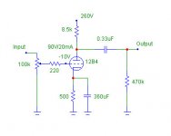
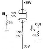
In the first pic I get the output signal from the Plate, and the Second from the Cathode!
Should I use the same way of output for Inverted or Non Inverted amplifier?
I need also some sugestions of tube buffers! I see tube buffers that work since 24v to 160v, what are the diferences in sound?
Thank you a lot !
edit: Please, read my other post above!

I'm looking for a tube buffer for my GainClone, so I started to search about it... I understood how tube works and everything, but I don't know yet the diferences between these two ways of output.
In the first pic I get the output signal from the Plate, and the Second from the Cathode!
Should I use the same way of output for Inverted or Non Inverted amplifier?
I need also some sugestions of tube buffers! I see tube buffers that work since 24v to 160v, what are the diferences in sound?
Thank you a lot !
edit: Please, read my other post above!
Attachments
Heh ! No problem with High Voltage, it's a buffer, so I'll not need a big transformer to get a high voltage, it's low current, right? I just want a cheap buffer that can sound well !
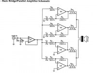
I'll will drive a BPA200 amplifier (LM3886 "200W" power amp), WITHOUT it's buffer. It have already a buffer in the manufactures schematic, because due the four CI's to be driven, the imput impedance is relatively low.
Thanks !!
I just want a cheap buffer that can sound well !I'll will drive a BPA200 amplifier (LM3886 "200W" power amp), WITHOUT it's buffer. It have already a buffer in the manufactures schematic, because due the four CI's to be driven, the imput impedance is relatively low.
Thanks !!
Dang, I didn't answer your question
The first one is the Grounded Cathode, which depending on the tube used, will give you gain, and phase inverts. You may want to look for the 12B4 linestage which some of us built.
The second one is the Cathode Follower and will not provide gain regardless of tube used, and does not phase invert. Decware has one based on 6N1P which you may want to check out.
Let's wait til the experts chime in to this topic
While we're waiting, I thought I'd just add my 2c. The second circuit, the cathode follower, has a much lower output impedance than the first circuit - maybe around 1 or 2k, depending on the tube. A cathode follower is useful to feed an interconnect cable.Let's wait til the experts chime in to this topic
Hi Nando
What are you expecting from the tube buffer? If you want 'tube' sound SY herethical line stage (buffer) won't work - search the thread and look at the distortion figures... Than it may be better to use an ECC88 with low voltage - a la Musical Fidelity Cans. Or Joe Rasmussen's buffer with ECC88.
Erik
Arnoldc ! Thank you for answering my question !
My idea is replace the buffer U5 in that attached schematic with the tube, so I go for non inverted. The gain can be one, like the U5, but if I can get a little more will be nice, two is fine!
The tube have to be the less expensive possible ! I shouldn't spend money on this project, I have others priorities heh ! BUT I'll spend some for sure ! Case, transformers and PCB are all already done and mounted! Today I'll buy the capacitors and resistors and put this thing to work !
I do not expect "sound tube" from the amplifier, I don't believe that chips can have this sound just because of a little tube in the middle of circuit... But, I expect more spaced sound, with less saturation ! Should I expect it? Not THAT sound, just some improvement.
Thank for all of you !!
My idea is replace the buffer U5 in that attached schematic with the tube, so I go for non inverted. The gain can be one, like the U5, but if I can get a little more will be nice, two is fine!
The tube have to be the less expensive possible ! I shouldn't spend money on this project, I have others priorities heh ! BUT I'll spend some for sure !
Case, transformers and PCB are all already done and mounted! Today I'll buy the capacitors and resistors and put this thing to work !I do not expect "sound tube" from the amplifier, I don't believe that chips can have this sound just because of a little tube in the middle of circuit... But, I expect more spaced sound, with less saturation ! Should I expect it? Not THAT sound, just some improvement.
Thank for all of you !!
Attachments
Hi there,
The second schematic, the cathode follower, will be a better choice. I think impedance is even lower than 1K. It is some fraction of the cathode resistance, if memory serves. Cathode resistances are usually some 300 to 600 ohms (1/transconductance).
Anyway, in this instance, you will probably get a warmer sound, simply because it is a tube.
Then, because feedback is considered to be a little over 100%, you would technically get no distortion.
So, you can concievably replace your U5 with the tube. But use the follower.
A buffer is defined as an amplifier with no voltage gain, but some current gain. So the cathode follower can take a 3-4 volts input at 0.05 milliamps and put out a 3-4 volt signal at 1-2 mA. In the case of the cathode follower, it has a slightly negative gain, which means if you input 2 volts, the output might be 1.8 volts.
Now, I would suggest using a 12AU7 or 12AT7, since you can set them up with a higher current output. They match your situation better.
Gabe
Hi there Nando,
I have a slightly different concern!
The circuit in your post #8: You have a very high amplifier input impedance as a result of the input voltage follower, so why "destroy" that with a low 10K input resistor. More serious for me is the input electrolytic capacitor (unless you use a relatively expensive polypropylene). I do not tend to get frenetic about the use of electrolytics as some, but a polyester is better here, and there is no reason (at least that I can see) for not using e.g. a 100K/330nF or even 220K/150nF. Would you still need a buffer then?
Secondly the cathode follower is better as already said, but I am a little worried about the low (35V) anode supply voltage quoted. I did not calculate, but it looks suspiciously low to put you in the high 2nd harmonic distortion operating area. (OK, you have full negative feedback; still.) If voltage is not a problem, for triodes I would personally prefer that to be over 100V.
But my first paragraph stands.
Regards.
I know so much little about tubes, that I read the posts and don't understand it perfectly 
I didn't understand about the impedance!
The output tube voltage drop isn't a problem if the sound is good.
I want to try the two sides of a tube, the most sweet warmer sound, and the most CLEAR, focused and spaced one!
I need hear this, I need know what kind of sound I prefer !
12B4 is the CLEAR right? What about the warm? I don't even know were do I get it on my country, anyway, I can import it if it's necessary, but I MUST try this !!!
That first schematic is 12B4 one, but it have inverted output right? How do I do to make it non inverted?
Thanks !!
If you want to replace U5, you NEED the low output impedance of the cathode follower to drive the combined input impedance of the bridge, which is around 500 ohms. That should narrow your choices. And the simple cathode follower has a gain of just below 1, not much you can do about that.
Even then, you need 40mA peak to drive that 500 ohms of the bridge to 20V peak, and that cathode follower will need to be able to do that without too much distortion. That means more than 40mA standing current in the tube for class A. Your example schematic can not do that at all. In fact, you will need some pretty specific circuit to replace U5 without loss of quality.
Jan Didden
That first schematic is 12B4 one, but it have inverted output right? How do I do to make it non inverted?
You can't. It is the nature of the way it works. Same is true for an individual transistor.
If you want to make a voltage gain amplifier, which is what the top one is, not invert, you need two tubes. Both invert, so the output would then be non-inverted. But, you need something with higher current output.
As for what Jan said, I doubt that the impedance is that low for those amps that you would have to worry about so much current. The voltage to drive them to full output can't be much more than 3 or 4 volts anyway. Into 500 ohms, 3 volts is about 6 milliamps, idle current notwithstanding. Typical impedances for hi-fi power amps are from 5K to 50K.
It is not like a class A amp where you have to have a high idle current, because we are not taking the signal from the plate. If it were being taken from the plate, then it would be like a constant current source. We are taking the output from the cathode, which is like a constant voltage source. In other words, you can pull as much current as you need in a pinch.
Gabe
Gabevee said:[snip]As for what Jan said, I doubt that the impedance is that low for those amps that you would have to worry about so much current. The voltage to drive them to full output can't be much more than 3 or 4 volts anyway. Into 500 ohms, 3 volts is about 6 milliamps, idle current notwithstanding. Typical impedances for hi-fi power amps are from 5K to 50K. [snip]Gabe
Gabe, you are right, I didn't notice the 20x gain of the bridged amps. For 200W in 8 ohms you would need 28V peak at each output which would be 1.4V input. The input impedance IS 500 ohms as can be seen by inspection the circuit. So, that would be about 3mA peak. Thanks for the correction.
Jan Didden
The input impedance IS 500 ohms as can be seen by inspection the circuit
Well... yeah. It does tend to make the calculation of input impedance in that instance a wee bit complicated, since the NFB is directly at the input for two of the amps, but not for the other two.
I guess if one concludes that the indirect NFB makes the input impedance infinite, or extremely high in the two, then the 1K of the other two are the sole impedances to use, making it 500 ohms.
Don't have the formulae at my fingertips right now, but I suspect that it might be lower?
It looks like a car amp...
Gabe
Assume that the + and - inputs are at the same level. On the inverting ones, the + inputs are at ground, so the - inputs are also at (virtual) ground. Each has a 1k series resistor. 2 x 1k // gives 500 ohms. Parallel to that we see the two non-inverting + input impedances, but these are very high and can de disregarded.
Make sense?
Jan Didden
Make sense?
Jan Didden
Hi:
If I were to connect a tube buffer to this bridged amp, I'd do it as follows:
1) I'd increase the input impedance of the output amplifier by factor 10 (i.e. increase the values of the input and FB resistors by factor 10);
2) I'd then recalculate the values of the input capacitors of the output amplifier accordingly;
3) in order to drive the ECC88 more adequately, I'd replace the cathode resistor with a FET current source set to approx. 7-8 mA;
4) B+ supply would be approx. 70V, derived from the power supply of the output amplifier (tripler + regulator);
5) the current source would be fed by the negative power supply (-15V, regulated);
6) I'd incorporate a delay circuit, which would isolate the output amp from the buffer for about 10-30 seconds when the power is turned on.
Regards,
Milan
First, I want apologise me, I was out some days and I couldn't answer the topic!
Second, I want thank you all because of the interest on the topic, and the help that you are giving to me!
About the gain bellow one, I need a High sensivity, I'll use it with guitars, and the signal from it is very low. I built a 3886 based circuit, with a 22K resistor for the feedback, and the sensivity wasn't enough to drive the amp to 100% of output power !
So I have two alternatives. The first, is use a IC buffer, just as the schematic shows, with more than 1 of gain. Of course, a good buffer, OPA2134 for example, and use the tube "buffer" before the U5.
The other, is use bigger feedback resistor value, so I can increase the amp sensivity.
BUT ! You said:
"Your example schematic can not do that at all. In fact, you will need some pretty specific circuit to replace U5 without loss of quality."
So, If I use a IC buffer like the schematic shows (U5), and a tube buffer (another buffer hehe) before it!? Will the tube sound be more far away yet?!
Gabevee I didn't understand very much your post ! I'm completely new with tubes, and not so experient with chipamps. The amplifier is done, except for the resistors that I didn't buy, because I don't know how many of gain I'll need, because of the tube buffer.
Oh god, I'm confused !
So now is possible to use a tube buffer from my schematic example?!
1° So, 10K of input resistor and 200K of feedback one !? I don't think that increase the FeedBack resistor by a factor of 10 is possible. Its incredible high gain, and probabily the IC will be unstable !
2° Why? What are the calculations ?
3° I don't know yet what tube I'll use ! It must be cheap ! So, don't think yet about driving a specific tube like ECC88
4° Don't worry about the supply. I'll get the needed voltage for the tube that we are going to choose !
5° No problem at all
6° Why?
Sorry about the long post, I'm new and I have to implement it !
We can't forget that I want to have distortion from the tubes too! Can I have a potentiometer to choose from the clean sound to the distorced?
Thank you VERY much !
Second, I want thank you all because of the interest on the topic, and the help that you are giving to me!
janneman said:If you want to replace U5, you NEED the low output impedance of the cathode follower to drive the combined input impedance of the bridge, which is around 500 ohms. That should narrow your choices. And the simple cathode follower has a gain of just below 1, not much you can do about that.
Even then, you need 40mA peak to drive that 500 ohms of the bridge to 20V peak, and that cathode follower will need to be able to do that without too much distortion. That means more than 40mA standing current in the tube for class A. Your example schematic can not do that at all. In fact, you will need some pretty specific circuit to replace U5 without loss of quality.
Jan Didden
About the gain bellow one, I need a High sensivity, I'll use it with guitars, and the signal from it is very low. I built a 3886 based circuit, with a 22K resistor for the feedback, and the sensivity wasn't enough to drive the amp to 100% of output power !
So I have two alternatives. The first, is use a IC buffer, just as the schematic shows, with more than 1 of gain. Of course, a good buffer, OPA2134 for example, and use the tube "buffer" before the U5.
The other, is use bigger feedback resistor value, so I can increase the amp sensivity.
BUT ! You said:
"Your example schematic can not do that at all. In fact, you will need some pretty specific circuit to replace U5 without loss of quality."
So, If I use a IC buffer like the schematic shows (U5), and a tube buffer (another buffer hehe) before it!? Will the tube sound be more far away yet?!
Gabevee I didn't understand very much your post ! I'm completely new with tubes, and not so experient with chipamps. The amplifier is done, except for the resistors that I didn't buy, because I don't know how many of gain I'll need, because of the tube buffer.
janneman said:
Gabe, you are right, I didn't notice the 20x gain of the bridged amps. For 200W in 8 ohms you would need 28V peak at each output which would be 1.4V input. The input impedance IS 500 ohms as can be seen by inspection the circuit. So, that would be about 3mA peak. Thanks for the correction.
Jan Didden
Oh god, I'm confused !
So now is possible to use a tube buffer from my schematic example?!
moamps said:Hi:
If I were to connect a tube buffer to this bridged amp, I'd do it as follows:
1) I'd increase the input impedance of the output amplifier by factor 10 (i.e. increase the values of the input and FB resistors by factor 10);
2) I'd then recalculate the values of the input capacitors of the output amplifier accordingly;
3) in order to drive the ECC88 more adequately, I'd replace the cathode resistor with a FET current source set to approx. 7-8 mA;
4) B+ supply would be approx. 70V, derived from the power supply of the output amplifier (tripler + regulator);
5) the current source would be fed by the negative power supply (-15V, regulated);
6) I'd incorporate a delay circuit, which would isolate the output amp from the buffer for about 10-30 seconds when the power is turned on.
Regards,
Milan
1° So, 10K of input resistor and 200K of feedback one !? I don't think that increase the FeedBack resistor by a factor of 10 is possible. Its incredible high gain, and probabily the IC will be unstable !
2° Why? What are the calculations ?
3° I don't know yet what tube I'll use ! It must be cheap ! So, don't think yet about driving a specific tube like ECC88
4° Don't worry about the supply. I'll get the needed voltage for the tube that we are going to choose !
5° No problem at all
6° Why?
Sorry about the long post, I'm new and I have to implement it !
We can't forget that I want to have distortion from the tubes too! Can I have a potentiometer to choose from the clean sound to the distorced?
Thank you VERY much !
- Status
- This old topic is closed. If you want to reopen this topic, contact a moderator using the "Report Post" button.
- Home
- Amplifiers
- Tubes / Valves
- What are the diferences between these ways of output?