Hello folks!
Well, time to do amp designing
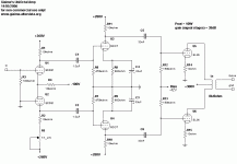
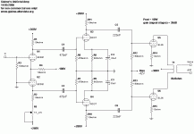
What do you think about it? Schematics attached.
I will finish soon designing the PSU: it will be SS rectification, capacitor input filter and LC filter.
I'm studying the possibility of building an amp that can let me exchange the output tubes: from a rapid look, 6V6 and its cousins would work.
You would ask: why so many coupling caps? Just DC-couple the first and the second stage. Well, that's an hard thing to do with only 300V B+, but if you have ideas please feel free to post them!
Gain is pretty high, I think I will add 3dB of global NFB from the secondary of the output transformer back to the (actually grounded) minus input of the LTP input stage.
Attachments
Yes Greg, I thought about it: but how can it be done with only 300V max B+?
You already have 200V at the ECC81 plate, you can have only 60V on the plate resistor of the 6CG7: of course cathode should be at some 210V above ground.
1) how could you bias a 6CG7 with those values?
2) where do I put the negative supply? I don't see...
You already have 200V at the ECC81 plate, you can have only 60V on the plate resistor of the 6CG7: of course cathode should be at some 210V above ground.
1) how could you bias a 6CG7 with those values?
2) where do I put the negative supply? I don't see...

Hello Tom,
I've downloaded the EL36-as-triode sheets at your site, and to get 50mA quiescent current I need about -50V, not too far from what TubeCAD calculated.
100mA at 300V I need at least -38V...
This surely imposes the interesting topic of the accuracy of TubeCAD calculations, but when the bias is regulated with a simple trimmer, frankly I don't see the point of the question
I'll need some more volts drive, that's not bad the driver can already do 70Vpk.
Hi Giaime,
Good argument, indeed!
Sorry for my misconception, but I just thought the values you gave in your schematic were measured / in vivo ones.
Tom
but when the bias is regulated with a simple trimmer, frankly I don't see the point of the question
Good argument, indeed!
Sorry for my misconception, but I just thought the values you gave in your schematic were measured / in vivo ones.
Tom
Oh excuse me for this Tom. No, the prototype hasn't been built yet.
Please don't use that schematic it hasn't been tested.
So, back to the topic: Greg suggested DC coupling. For me, it's not doable.
what do you think?
Are there other points I should improve?
Notice that I tried to take care of the phase shifting associated to the 2 coupling caps: in fact the time constants of the two RC couplings are very far from each other, I could increase them if you find it useful. I plan on having a 0.5Hz cut at the first, 5Hz at the second and 20-30Hz at the output transformer...
Please don't use that schematic
 it hasn't been tested.
So, back to the topic: Greg suggested DC coupling. For me, it's not doable.
what do you think?
Are there other points I should improve?
Notice that I tried to take care of the phase shifting associated to the 2 coupling caps: in fact the time constants of the two RC couplings are very far from each other, I could increase them if you find it useful. I plan on having a 0.5Hz cut at the first, 5Hz at the second and 20-30Hz at the output transformer...
Hi Giaime,
Probably hard to do with this tube selection (I mean the ECC81 in front, which needs quite some voltage across it and its plate resistors) and when not using a SS CC sink to make some voltage available which is burned in the tail resistor at the moment.
Regarding the time constants, they are not that critical at all, since you don´t show/use a gNFB loop (Poobah might have missed that in his article).
Tom
Greg suggested DC coupling. For me, it's not doable.
what do you think?
Probably hard to do with this tube selection (I mean the ECC81 in front, which needs quite some voltage across it and its plate resistors) and when not using a SS CC sink to make some voltage available which is burned in the tail resistor at the moment.
Regarding the time constants, they are not that critical at all, since you don´t show/use a gNFB loop (Poobah might have missed that in his article).
Tom
Thank you Poobah and Tom.
Well, I'd like to put 3-6dB of gNFB, but I've got to test on the real amp if the trannies are good enought to go without. So, how could I deal the phase shifts?
Tom, could you propose something to allow DC-coupling? My only limit is how much grid drive I need for the EL36 (at least 110-120Vpp) and the positive supply of 250-280V. No fear for sand
Hi Giaime,
You know my suggestions already from another forum, you can look it up there again, if you forgot
Tom
Giaime said:[Tom, could you propose something to allow DC-coupling?
You know my suggestions already from another forum, you can look it up there again, if you forgot
Tom
Tom,
you suggested ECL84 or similar for DC-coupled gainstage follower by LTP.
If I wouldn't use those tubes, and would like to follow the way of LTP first, gain stage after, what tube could I use?
I need a tube that does phase splitting with low anode voltage, isn't it?
I could use ECC88, I can have 95V on the anode with respect to ground. Or 5687, up to 90V. In general, as I understand, high gm tubes is what I want here.
So, taking account of 95V at the grid of the 6CG7, I need 98V on the cathode, and on 6mA this is 16k cathode resistor. Now, I want something like 120V across the tube, so plate voltage should be 220V, and using a 10k resistor at 6mA I need a B+ of about 280V, that's pretty doable.
It sounds good to you? Notice that doing so I have less driving capabilities, only about 32Vrms where I need at least 40Vrms.
I could also use the 5687, same guessings. I want to run it at 8mA, 10k load and about 105V across the tube: so 12k5 cathode resistor and 285V B+.
Take a look at the ECC85, it is designed to operate at extremely low plate voltages and has reasonably good linearity, particularly when compared to ECC81. This should allow you direct couple to the following LTP..
I did something similar years ago with 6SL7 LTP and 6SN7 LTP, but the supply voltage was 400V. Regulated supplies were required to keep everything happy as the design was not tolerant of very large variations in supply voltage. Still works fine, not fussy at all over tube matching. See my site if you are curious.
Regards, Kevin
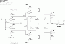
So, I've ended up with something like this, schematics attached.
If I regulate the 150V supply (0D3 comes to mind) and if I add a 500ohm trimmer in series with the cathode resistors of the 5687 (dissipation would be negligible here), I think I will have sufficient stability and the possibility to dial the exact amount of current I need for maximum linear swing.
With this configuration, I have pretty much all the driving voltage I need, in fact it's in excess of 50Vrms.
Edit: corrected schematics, coupling caps increased to 220nF.
Attachments
Dear green cap friend,
That's getting closer...
Look at R2... R2 should be maybe 9.1 K and the pot just below should be 2 K. You want 40% of the pot value plus R2 to equal the other "side" of the diff amp.
Some would say your balancing pot should go in the cathode portion of the circuit as well.
Also the balancing network might be better in the second stage and not the first. The second stage has larger voltages swings and balance will be more cirtical.
Dear pre-amp basher friend,
Thank you. I will follow your suggestion of the balancing network on the first stage: do I need a balancing pot on the cathodes of the first stage? (wiper connected to the tail resistor, each other leg to the ECC88 cathodes).
And surely, I'd like to implement a balancing network on the second stage. What form should it be? A shunt trimmer (wiper to ground) maybe 200-470kohm between each out-of-phase signals? Or it would be better to use a single trimmer to vary one of the 5687 anode resistors?
Giaime,
Search for a threar called "change my quicksilvers to this?"
It has a very similar layout... cascaded diff-amps... also some SY/Morgan Jones tricks...
Keep in mind, I am not convinced that the coupling caps are so bad. The second stage voltages get very high in this design.
Your green-cap-only-bashing-friend,


Search for a threar called "change my quicksilvers to this?"
It has a very similar layout... cascaded diff-amps... also some
 SY/Morgan Jones tricks...
Keep in mind, I am not convinced that the coupling caps are so bad. The second stage voltages get very high in this design.
Your green-cap-only-bashing-friend,
Thank you Poobah, I will search the thread and learn what I can.
Mmm... me too, but I don't see the problem in doing some more work and put them out of the circuitry. Also, I don't understand why it's a problem to have high voltages at the second stage: do you mean I will have trouble in filtering (too few volts to burn)?
poobah said:Keep in mind, I am not convinced that the coupling caps are so bad. The second stage voltages get very high in this design.
Mmm... me too, but I don't see the problem in doing some more work and put them out of the circuitry. Also, I don't understand why it's a problem to have high voltages at the second stage: do you mean I will have trouble in filtering (too few volts to burn)?
- Status
- This old topic is closed. If you want to reopen this topic, contact a moderator using the "Report Post" button.
- Home
- Amplifiers
- Tubes / Valves
- Giaime's new toy - aka the UniOctal


 but probably only for a few minutes
