@ray_moth: how are your experiences withe 6d22s??????? they're not too expensive and could maybe very well substitute for my py500A's???
My experience, having used them for a couple of years, has been very good. Forward voltage drop is about 15v at 250-300mA. The heater requires 6.3v @1.9A but, according to Svetlana, they will work well even with only 5v. Maximum heater-cathode voltage is 600v, which means the heater can be safely fed from the normal grounded 6.3v supply used for other tubes, if you wish. As you say, this is an inexpensive rectifier and, given its superior ratings in all respects, it makes more sense to me than something like a GZ34 if you need high current.
The 6D22S is a glass-based single diode (i.e. you need 2 of them). It needs a magnoval socket, which is like an octal-sized B9A socket. Its only disadvantage is the top cap cathode connection, which means that you have to be careful to ensure that it can't be touched accidentally. The ceramic-shielded cap supplied for this purpose works well. I bought my 6D22S tubes, sockets and top caps from Amplimo in the Netherlands.
Thanks Ray-moth!, i had also seen them at amplimo's site....
i'll keep them in mind for replacing the py500A's (42v, 300ma heater) when they are worn out....!
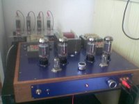
got the sockets etc...
(even on this bad picture you can see the 'blackish' residu around the top caps, sorry don't have a close-up)
i'll keep them in mind for replacing the py500A's (42v, 300ma heater) when they are worn out....!
got the sockets etc...
(even on this bad picture you can see the 'blackish' residu around the top caps, sorry don't have a close-up)
Attachments
teocc_1308 said:To confuse this issue a little.
I just read on following
Source: http://yarchive.net/electr/tube_time_delay.html
"One common argument used by tube rectifier aficionados is the so-called cathode stripping effect where high voltage applied to the plate of a tube before the cathode has warmed up can strip the cathode of emitting material.
Unfortunately, this effect only occurs at high voltage, typically above 10
kilovolts. It is not a factor in small receiving or transmitting tubes.
If it really were a problem, it would destroy the tube rectifiers which have plate voltage applied immediately at turn-on.
It's only affect tubes typically >10 KV, while not affecting small signal tubes or transmitting tubes.
Just wondering is there any official research or paper publication to precisely define this concern ?
Thank & regards
That's exactly where I was going...and I am currently running some 40 year old pulls that still test like NOS ones in my amp's ps( they are f32-type GZ34's ). This cathode stripping thing seems like a booogey-man story for frightening small children...
")
cheers,
Douglas
Well, here's what's missing: a wide-ranging statistically valid comparison for some typical usage. Everything published is either very narrow and specialized or purely anecdotal. For me, the long life of rectifiers is a pretty strong strike against the cathode stripping hypothesis at less-than-kV-levels with metal oxide cathodes.
My anecdote is that I've not seen any significant difference in tube life between things I've built/owned that turned on rapidly versus slowly. If something ate tubes (and I built a LOT of gear that ate tubes!), it always turned out to be for a different reason.
I say this just as I finished doing some comparative measurements in my EL84 amp using a set of new JJ EL84 and some ancient United Electron 6BQ5/EL84 (date code 1966). The UEs were pulls from a salvaged Dynaco SCA35, solid state rectification, instant on- folks my age will fondly remember the mechanical thump at switch-on. They'd seen a lot of on and off in the twenty years or so in that amp. On test, they showed the same power out and quite similar 1kHz THD compared with the new JJs. The old tubes' idle current was a bit higher at the same bias voltage. Cathodes would seem to be intact.
Sample of one. But still, one more data point.
Hi
As most others members contributing to this thread I am doubting, that cathode stripping happens during warm up. If it would be the case many tubes would have a shortened life and practically all tube amplifiers using solid state rectifiers would have short tube life which is as I understand not a common experience.
However, cathode stripping can happen in other cases like when the cathode current rating is exceeded, it seems to be so that different tubes have very varying margins when it comes to cathode emission and some tubes seem to be operating very close to safe values.
My father who at one time was responsible for maintaining the tube database for the Swedish navy, (maintaining which tubes that was recommended to use and recommended operating conditions) one time experienced the phenomena of cathode stripping. The tube in question was 807 and it was used in a public address system aboard some newly built battle cruisers, (this was in the early fifties).
The amplifier was designed to operate in a certain load impedance which of course a cathode current within safe range, (class B). What happened was that some one who was responible for the public address system, (but obviously not with any knowledge of electronics) added more speakers in parallell reducing the load impedance until the point where probably the anodes was glowing red and the cathode surface started to break up.
The amplifiers failed after very short time in use and the cause of the problem was investigated, during this investigation some tubes was dismantled and photos was taken of the damaged cathodes. I have somewhere one of these photos but due to me moving around I have currently no idea where it is, If I find I will scan it and post it here.
Regarding different tubes having varying safe margins I believe that 6C33C is a good representative of a tube with very good margins, the tube is designed for a continous max current of 600mA but I have run this tube at 2.5A peak current, (BTW this is not the saturating limit) without any ill effects. The heater power of a 807 is 5.7W and the safe operating current is 125mA, so the relative heater power is 0.0456W/mA, for the 6C33C the heater power is 41W and a cathode current is 600mA so relative heater power is 0.068W/mA this difference together with the fact that 6C33C is a much more modern tube could possibly explain the difference.
Regards Hans
SY, I've never noticed those ratings. Are there any examples on the web?the number of data sheets that rate maximum plate and screen voltages for the cold tube.
The amplifier was designed to operate in a certain load impedance which of course a cathode current within safe range, (class B). What happened was that some one who was responible for the public address system, (but obviously not with any knowledge of electronics) added more speakers in parallell reducing the load impedance until the point where probably the anodes was glowing red and the cathode surface started to break up.
Being that I am employed in the commercial sound field I have experienced many instances where the load was way beyond the power capabilities of the amplifier. One such occurance was a newspaper company that had a 70 volt commercial Bogan amplifier with a load of 10 ohms on it. That translates to a 500 watt load. The amp was a 50 watt Bogan. No cathode stripping occured with its 807 output stage.
I repaired the fault which ended up to be an offending speaker down the line without a transformer. The amplifier to this day continues to run, transmitting music and pages. Still has its 807 tubes in it.
My thought is cathode stripping might occur when signal is
applied before warm up has occured.
Afaik, cathode stipping occurs only with directly heated tubes, if it occurs at all. Indirectly heated tubes are rather immune to this disorder, afaik.
I think the issue is that the filament has thorium embedded on the surface, not alloyed into the tungsten. If the thorium is "stripped" from the surface, "she's-a-no-work".
An old timer's ham radio "trick" for tubes with low emission was to overheat the filaments for a short period of time, to bring more active thorium to the surface. It didn't always work. But was worth a shot.
At least this is my foggy understanding...
_-_-bear
PS. fwiw, many transmitting tubes have in their data sheets the requirement to preheat the fils for 60secs or more... they are directly heated. Many do use B+ in the kv range.
I suspect the 6AS7, 6080, 6C33 and some other high perveance low mu triodes are quite susceptible to cathode stripping based on very limited experience I'll admit - mostly I have observed a loss of emission over a relatively short span of time. (months) I have also discovered to my chagrin that in otl designs any of these can arc over during warm up if B+ is not delayed and this is much more of a concern.
300B may be prone to cathode stripping as well, but I have not really witnessed this so far. Other issues seem more likely to kill one frankly - mostly qc in current "affordable" versions.
I design most of my amplifiers to delay B+ to any output tube that costs an appreciable % of my weekly take home pay..
I have never seen evidence of cathode stripping in any EL34, 6550, KT88, 6L6, 6BQ5, 7189..
This should not be taken as anything but anecdotal, I have not been systematic or scientific to any degree.
'modified' standby?
One method previously discussed in the forum is to apply 'modified' standby switch. In standby, small voltage (half of full B+) is bypassed so that the plate doesnt experience the full 'shock' once it is turned on.
My tubes are cheap anyway so I dont really bother...
One method previously discussed in the forum is to apply 'modified' standby switch. In standby, small voltage (half of full B+) is bypassed so that the plate doesnt experience the full 'shock' once it is turned on.
My tubes are cheap anyway so I dont really bother...
Sleeping sickness in tubes, B+ but no heater story
Sleeping sickness can happen with tubes with heater voltage applied, but no current drawn, or B+ without heaters on, for long periods of time. Somewhat related to cathode stripping.
Quoted from the usenews newsgroup rec.audio.tubes, written by DeserTBoB:
>Bob, are you sure "Sleeping sickness" also occurs when B+ is applied
>>without "filament" power? I never heard of that before, although that
>>clearly doesn't mean it doesn't happen. <snip>
Yes, it does! I witnessed this happen one time which resulted in an
supervisor earning a little unpaid vacation time.
Old multiplex equipment associated with Types J, K and L carrier
systems used by AT&T's various companies built in the '40s and '50s
used basically two tubes...the 311B triode, and the 310A sharp cutoff
pentode, essentially a five prong, 5 V filament 6C6, for anything
below the mastergroup MUX level. Above that, the 404A (basically a 5V
6AK5) and the 417A single triode were used for mastergroup gain and
stacking. One day, a migration to IC-based equipment on another floor
occurred in our office, the largest carrier office in the US,
rendering an entire floor's worth of antique channel modems, group
demods, supergroup demods and all associated equipment such as carrier
supplies to be relegated to "spare" status. A transmission man
working that floor, trying to earn a few "brownie" points,
disconnected all the -24V filament battery at the BDFB to all this
gear. Laziness and timidity precluded him from removing the +130 and
+315 plate supplies. Thus, over 750 311B and 310A tubes were left in
situ with their usual B+ on the plates and cold filaments.
About three months later, a surge in traffic demand prompted the
circuit provision bureau to reassign new multiplex facilities to this
equipment, and within a short lead time. When such work happens, the
"circuit order" worker tests the gear both directions, sets levels as
appropriate and checks for basic transmission impediments. In this
case, the equipment didn't pass tone anywhere and wouldn't mod or
demod anything at all, and a trip to the BDFB found boxes of 1 1/3 amp
grasshopper fuses all placed neatly on the floor in front of the fuse
bay. After replacing all the filament supply fuses, the equipment
still failed, but some of it would pass modulated/demodulated signal,
but at bad levels and with not nearly enough gain to meet
specifications. After some checking, they called me down to try to
figure what happened.
Western Electric gear from that era used an "in service" tube test
regimen that looked basically at plate and filament current and
"filament activity" (an old term that really meant "cathode activity"
in anything other than direct heated tubes.) The in service tests
showed acceptable filament current, but the plate current was either
gone or very weak. In cases where there was at least some plate
current, dropping the filament current 10% wouldn't cause a dip in the
plate current...odd. A trip to the Hickok Cardmatic (KS version, of
course) showed all the tubes on the entire floor to be "dead" for Gm.
That's when the "brownie" said, "Oh...well, I took all the filament
fuses out of everything to save power. I reported it to my boss, and
he put an attaboy in my folder." A little investigation proved this
to be true, and the supervisor was given some time off for being an
idiot. A look at the Bell System Practices relating to vacuum tubes
specifically stated that at no time should any tube of any
configuration, except for cold cathode tubes, be allowed to stand with
B+ on any element without the filament being hot.
Some further investigation with the folks at the Littleton, CO WECO
tube plant confirmed that running any tube with the plates energized
and no filament will cause the same, or worse, symptoms as "sleeping
sickness" generally attributed to having a tube run in cutoff for long
periods of time. In short, what happens in either case of "sleeping
sickness" is that the plate winds up acting as a getter, thus becoming
unreceptive to electron reception from the cathode after being plated
with contaminents within the envelope. That explained immediately why
the tubes, while testing bad for Gm, tested good for cathode activity.
This was further confirmed by the fact that newer tubes were still at
least conducting something, while tubes that were some 30-40 years old
were completely dead on test, although the records showed their last
"in service" current test to be well within specs. Conversations with
retiring engineers at the tube plant confirmed that no "real life"
vacuum tube had a very good vacuum in it, and even if it had one, it
would be partially destroyed during the initial aging process by
gasification of the tungsten on the filament and thorium from the hot
plates. That's why tubes have getters in them, after all. As the
fellow told me, "You cut off electron flow, and that plate makes a
really attractive getter...the higher the B+, the more it "gets!" Add
to this that the cathode, grids and filaments are all at or near
ground potential, and you see how this can happen to the plates.
In the final tally for this goof, over 350 310A tubes, at $150 a pop,
and 200 some odd 311Bs, at $75 a pop, had to be replaced on an
emergency basis. At the time, Western Electric was getting out of
tube manufacturing altogether, and the assembly and aging lines for
the old ST envelope tubes were out of commission while the equipment
was being sold to Richardson Electronics. As it turned out, a canvass
of toll offices across the country had to be done to mine every
available 310A and 311B, even old "pulls" from retired equipment, to
get the MUX gear back into service. As it was, the due date for the
facility additions was jeopardized by over two months, and the carrier
group responsible for the gear (ours) had to buy all new Richardson
tubes for the offices which gave up their spares. Total cost of the
fiasco: over $130,000. There was little solace in the fact that the
removal of the filament battery saved about $500 in power costs. To
add insult to injury, the equipment only carried the service for
another six months before being finally retired and scrapped.
"Audiophools" worrying about "cathode stripping" has nothing whatever
to do with "sleeping sickness." I've yet to see any "audiophool" who
actually knows how a tube works, anyway. You have to expect this from
people who refer to audio phenomina as "air," "stage," "detail,"
"crispness" and other assorted laughable terms.
dB
Sidebar: On that particular floor resided many old pieces of gear
from the 1930s, including bays of voice order wire equipment
associated with long gone J and K carrier systems. In them were rows
of bayonet based 101D triodes and 201As, most dating from the 1930s,
some from the '40s. All tested good when pulled after 45+ years of
continuous service. I shudder to think what these old things would've
brought today on fraudBay. The secret to long tube life at the phone
company? Running filaments 10% below rated voltage and excellent
quality elements. The Richardson replacements which came later were
nowhere near the quality of any old WECO tube, and WECO tubes made in
the early '80s were almost as bad.
Hmmm, interesting. However, whilst others have expressed doubts that the thin emissive surface of an oxide-coated cathode can be damaged by ion bombardment, I have misgivings about this explanation. It's reasonable to assume that the positively charged anode will attract any contaminant floating around in the supposed vacuum, but if those contaminants are thorium and tungsten then they're still conductive and I don't see any reason why they should stop the plate from working. We'd need some insulating contaminants to react with the anode surface and produce a hardy insulating layer that can't be damaged by an accelerated electron. Nickel oxide or nickel nitride? Thoughts from the chemists?
I'm also doubtful that the longevity of telephone exchange valves can be attributed to running their heaters at 10% below the manufacturer's stated value. I'm more inclined to believe that small-signal valves run well below their maximumm anode dissipation lasted a long time because they were never switched off. That was certainly my experience at the BBC where we had valve telecomms equipment like voice frequency ringers and associated oscillators permanently powered.
However, all this has got me thinking that when valves are run well below their maximum ratings that perhaps it's letting them get cold that kills them. When the valve is cold, the getter is no longer active, but the valve still leaks air, just as a bicycle tyre or balloon leaks air. Obviously, the process is much slower, but it does mean that each time the valve is switched on, it has to operate with excessive gas until the getter can mop it up. I can see a thousand or so cycles of this form of operation killing the valve, whether by cathode stripping or by plating the anode with an insulator. Support for this hypothesis is given by the fact that valves in continuous operation last a remarkably long time, and perhaps also by the fact that valve audio seems to take at least half an hour from switch-on before it sounds at its best (the grid current caused by the excessive gas would increase distortion).
It should always be kept in mind that what looks to be a physically robust system (the cathode) is fairly fragile at the atomic and molecular level. The requirement of ultra pure materials for the construction of a successful cathode and the fact that it is easily poisoned by contaminents should be an indication of this.
Also keep in mind that Alan Wright was referring mostly to noise from tubes amplifying very low level signals as being the result of damage from ion bombardment (at least this is how he explained it to me), not loss of emissibility of the cathode. So damage is small but noticeable.
Furthermore, tubes with heavy cathode coatings often have specified warm-up times before application of plate voltage indicated in their respective engineering bulletins. I personally have confidence in the men who wrote these specs.
http://frank.pocnet.net/sheets/131/6/6106.pdf
P.S. Curiously, on amplifying tubes, Bendix footnotes cathode warm-up time with "plate and heater voltage may be applied simultaneously". Rectifier tubes don't show this footnote.
John
That's why tubes have getters in them, after all. As the fellow told me, "You cut off electron flow, and that plate makes a really attractive getter...the higher the B+, the more it "gets!" Add to this that the cathode, grids and filaments are all at or near ground potential, and you see how this can happen to the plates.
It seems to me that having the getter attached to the plate (as most tubes do) would help preclude this, if there is any getter material left in the ring.
John
Cathode Stripping
Cathode stripping isn't really a literal stripping of the cathode, but, as mentioned earlier, a bombardment of the cathode by positively-charged ions at a point during warm-up where there is enough cathode emission to start a flow of electrons, but not enough to form a "space charge" around the cathode, which tends to protect it from the positive ions. Since the ions have a large mass relative to the electron, they can physically damage the cathode coating, which is quite fragile. When the cathode is activated during manufacturing, trace elements migrate to the surface and create the efficient electron emitting layer. Without activation, an oxide-coated cathode is essentially inert. Also, certain ions, such as sodium and sulphur, can "poison" the cathode, causing much worse damage than just routine stripping. The usual effect of cathode stripping is a shortening of the useful life of the tube, although rectifiers can create fireworks inside during warm-up.
Thoriated-tungsten cathodes are also susceptible to cathode stripping, since they have a monatomic layer of thorium on top of the tungsten that can be damaged by positive ions. However, by running the cathode over temperature, new thorium can migrate to the surface. The schedule for re-activating thoriated-tunsten tubes differs, depending if the filament is "carburized" or not. I believe that most modern thoriated tungsten tubes (211, 845, 811A, etc.) are carburized. Pure tungsten filaments are immune to cathode stripping, but these are rare and were only used for very high-voltage tubes.
Contrary to the urban myth, gas (at least our atmosphere) doesn't leak through glass. Helium can permeate through glass, but is rather slow. According to Kohl's Materials and Techniques for Electron Tubes (1960), the permeation velocity of helium at 100 degrees C through lime glass (used for the bulb) is about 10E-13. (Permeation velocity is ml of gas per second per cm^2 per mm of thickness.) Atmospheric gasses are essentially impermeable. Most gas in a tube comes from degassing of glass and metals caused by heating during operation. The getter coating does work all the time, but will work better at higher temperatures, up to a point. Gas is reduced in a tube during operation by a process called "clean-up" which is essentially the gas molecules getting trapped in the plate by electrons hitting the plate. An existence proof of the impermeability of glass are the N.O.S. tubes from the 1920s and 30s that work just fine out of the box.
A delayed B+ turn-on is a good idea, especially for power tubes. An alternative, which I have used in some of my designs, is to apply a high negative bias to the grid during warm-up, then after a delay, drop the bias to the normal level. With the high bias, the tube is cut-off, and any stray positive ions would go to the grid, thus the cathode is protected. This works well with the Amperite thermal time delay relays, which cannot handle much current.
- John Atwood
Contrary to the urban myth, gas (at least our atmosphere) doesn't leak through glass.
It does, albeit slowly. It is much slower through metal than glass, which is why glass is generally not preferred for high vacuum systems that must be disconnected from their diffusion pumps for long periods of time. The other weak points are the glass pinch-off and glass-to-metal seal. Normally in high vac systems used in catalysis and synthesis, there is a much stronger getter than one sees used in tubes- NaK alloy is probably the gold standard (so to speak). Mercurial, its surface can be continually renewed by tapping the container it's kept in to remove the slag.
I have samples of VERY air sensitive materials (specifically, n-doped polyacetylene and poly-p-phenylene) well-sealed in glass tubes (no getter) which deteriorated over the course of 5 years. I suspect the slow diffusion rate plus the presence of getter is why very old tubes often still work well.
hi all,
cathode stripping occurs when its' temperature is too low. Always respect the heater voltage specification within +/-5%.
best
Guido
If that were the case, no IDH rectifier would survive turn-on.
cheers,
Douglas
- Status
- This old topic is closed. If you want to reopen this topic, contact a moderator using the "Report Post" button.
- Home
- Amplifiers
- Tubes / Valves
- Doubts on cathode stripping in tubes