A collection of 811 schematics was recently posted in another thread: http://www.diyaudio.com/forums/showthread.php?s=&threadid=79034 . Among them is the circuit shown below. What's the story behind the 6GB8-811A coupling? The same topology appears in many posted Japanese amps and I can make some sense of it - 811A grid positive, driver plate quiescent current = output grid quiescent current - but loadlines, optimization, even name are a complete mistery. The latter especially mades it real difficult to learn more. Anyone point me towards an explanation? Thx in advance!
Attachments
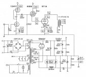
It looks like an ordinary cathode follower. If the output stage is running in A2, you don't need a cathode return resistor or CCS. And because of the degenerative nature of the CF, you just optimize the output stage in the usual way, then set the CF's grid voltage accordingly. Variations in output stage grid current are soaked up by the CF.
edit: the CF grid voltage is set to zero, so the driver tube would have been chosen to get to somewhere around what the required grid voltage of the 811 is for A2 at that supply and load, with Rk taking out the criticality.
edit: the CF grid voltage is set to zero, so the driver tube would have been chosen to get to somewhere around what the required grid voltage of the 811 is for A2 at that supply and load, with Rk taking out the criticality.
Thanks SY. As a first approximation is the method to divide the output stage grid voltage by static grid current and call that the driver cathode 'resistance'? I'm not sure I see the advantage of dropping the cathode resistor beyond reducing supply current, and perhaps permitting a less robust driver. Designing for startup conditions must also be a hoot, hence the use of SS reciftifiers for the driver supply.
rdf
Another easier way is to use 6BQ5(or 6BM if you want to to use 1 tube less) to drive the 811A tube. It uses the cathode of 6BQ5 to drive 811A. One of the collections uses 6BQ5. I was told that 811A's grid draws 10-30mA(I believe it would less than that) when it is operating, you can experiment with 6BQ5 which easily available.
If you don't have this circuit diagram, leave a message here I will email you.
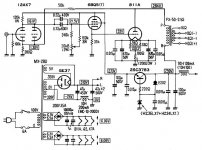
Thanks for the generous offer ttan98 but I still have an EL84, a GU-50 and an 828 (if things work out) to complete before looking at A2.  Is it the circuit below? To be honest, especially after reading John Broskie's take on cathode followers, I'd be inclined to consider something with more meat for the task. The RCA sheet shows an 811 draws big current at plate voltages below 200 vdc. For this circuit at max positive swing (say 60 volts) my guess is it approaches 80 ma.
Is it the circuit below? To be honest, especially after reading John Broskie's take on cathode followers, I'd be inclined to consider something with more meat for the task. The RCA sheet shows an 811 draws big current at plate voltages below 200 vdc. For this circuit at max positive swing (say 60 volts) my guess is it approaches 80 ma.Attachments
811A grid
As far as load lines, the 811A's grid looks like a 1K ohm
resistor when it's running in Class A2. In order to drive this,
you need to load it down with 300 ohms or preferably alot less.
Further, the load is going to have to be able to sink the current.
If the 811A's grid is 1K ohm, then then the load (aka driver tube),
has to take on 1 mA of additional grid current for each 1 V of
swing. 1K = 1 V/1mA")
Thats why you use a CF.... The impedance is so low that it can
move the 811A's grid nicely. Anything that has a gM >> 1mA/V
will work dandy. An EL84 would be killer - since it has a very high Gm. As it turns out, the 6V6 is plenty good too.
As far as grid current, you are correct, the lower the Anode B+,
the higher the Ig. That's because at lower Anode voltages, the
grid can outcompete the anode for attracting electrons because of its proximity to the filament. If you look at the grid current curves for these tubes, you will see the relationship.
There's other stuff besides a cathode follower... How about
a MOSFET?
As far as load lines, the 811A's grid looks like a 1K ohm
resistor when it's running in Class A2. In order to drive this,
you need to load it down with 300 ohms or preferably alot less.
Further, the load is going to have to be able to sink the current.
If the 811A's grid is 1K ohm, then then the load (aka driver tube),
has to take on 1 mA of additional grid current for each 1 V of
swing. 1K = 1 V/1mA
Thats why you use a CF.... The impedance is so low that it can
move the 811A's grid nicely. Anything that has a gM >> 1mA/V
will work dandy. An EL84 would be killer - since it has a very high Gm. As it turns out, the 6V6 is plenty good too.
As far as grid current, you are correct, the lower the Anode B+,
the higher the Ig. That's because at lower Anode voltages, the
grid can outcompete the anode for attracting electrons because of its proximity to the filament. If you look at the grid current curves for these tubes, you will see the relationship.
There's other stuff besides a cathode follower... How about
a MOSFET?
One more thing...
You shouldnt be afraid to play with an 811A... One nice thing
about these tubes is they are pretty much failsafe. It's nearly
impossible to blow out an output transformer from an oopsie.
If you foul up the bias circuit, the 811A pretty much stops conducting. If you overbias the 811A, the only part at risk
is the driver tube.
You can also use the 572B which has the same pinout, filament
needs and specs as the 811A.
lndm said:I wonder, wouldn't the CF drop out of circuit if the 811's grid went negative and stopped passing current?
SY, is this anything like the setup you mentioned in that other thread?
Yes, the CF's load shoots up to (essentially) infinite when the output tube cuts off- which it isn't supposed to do in A2. The CF won't drop out, but whatever is coming out of it is moot.
SY said:
Yes, the CF's load shoots up to (essentially) infinite when the output tube cuts off- which it isn't supposed to do in A2. The CF won't drop out, but whatever is coming out of it is moot.
Yes and that is the reason to use the most (IMHO) practical and effective way to load the CF: A choke from cathode to ground, direct coupled to the grid of the output stage.
In case that the cathode voltage is higher than desired, one can compensate with the cathode resistor of the output tube.
Greetings
Konstantinos
I'll take a wild stab: keep DC current flowing through the driver when the output grid nears cathode voltage with minimal AC loading of the CF in normal operation. Not sure if it's important though it does seem to be a consequence. Could there be a driver recovery benefit from never letting it pinch off? I know little about A2 biasing.
A resistor and choke permits a higher minimum current without loading down the driver in normal operation. A resistor gives one or the other. That's why I wonder if builders justify it on the basis of recovery. The driver can be set to never go below a specified current during overload and is always ready when the ouput tube starts asking for current again. Doesn't the plate impedance of a tube skyrocket at microamp plate currents? Some of the 811A schematics specify a B+ under 300 Vdc so overload is probably a significant consideration in those designs. Then again, never having built one I really have no idea. Harder than wild guessing is resisting the urge to FleaBay and find out.
rdf said:Doesn't the driver current go to zero as the 811's Vg approaches Vk (for a follower connected only to the output grid)? I think it's the other end, at max positive swing, where the driver takes a beating.
From a current standpoint, yes, but voltage also goes down as you swing positive. That's why you want a driver with high perveance. Or commit heresy and use a MOSFET, which is happy to pump current at low D-S voltages.
Guys,
For those who do not want all these problems, use SV811-3 the normal operating grid voltage is 0(for cathode), and it is operating in pure class A. eg, at VA=430V, Vk=-75V, Ia=75ma, this tube can put out 12W at this settings. It is made by Svetlana, and it is not cheap.
Those who want the data sheet see below
Attachments
- Status
- This old topic is closed. If you want to reopen this topic, contact a moderator using the "Report Post" button.
- Home
- Amplifiers
- Tubes / Valves
- Interstage topology question