I changed from the 6l6GC to the EL34 because It seemed like a better tube for me. it had more power in Triode form, and A higher plate voltage. However I wanted to ask you guys what you think of EL34s as an SET because I have noticed some things very odd about my amp
The bass response is rather excellent, it really thuds
however, the higher bass spectrum (probablly around 100hz-500hz) sounds really poor when the volume is about three quaters of the way up.
I am using cheap Hammond 125CSE transformers, and cheap out put caps, are my problems in those cheap components?
Will I be happier investing a good 40 dollars in slightly less cheap center-tapped transformers to change to UL or Pentode? Any help would be much appreciated
more info
It's hard to give advice with so little information and most everything is so subjective in listening, especially when no measurements are given.
The poor frequency response as well as the good response at various frequencies may not be soley due to electronic components. Room effects can have significant impacts on frequency response, too.
The caps and OPTs can have major affects on frequency response, no doubt. IME the OPTs have the most significant effect assuming the caps are sized properly, within the context that you have provided. Better trannys than those you described will give obvious improvements.
HTH
alexmoose said:Sorry about the low information level, I'll explain some more right now.
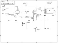
here is a look at the schematic with the preposed solution, using an NFB Loop with a Pot to limit the negative feedback, which it what I think the problem is
Try removing the bottom of the 1000 uF output tube cathode R bypass cap from the speaker output terminal and placing it to power supply ground. You could also try much smaller cap sizes here. 100-500 uF.
What rcavictim says is right.
With the EL34 cathode bypass cap wired to the speaker output terminal like this you have a reasonable level of feedback around the output stage itself and the driver is starting to strain under the output tubes increased drive requirement. This will show up mainly at higher volume settings.
At say 5 Watts Output you are having to swing an extra 6 V RMS (nearly 18 V pk - pk) to overcome this negative feedback.
If you want to keep that quite elegant scheme then you'll need to beef up the driver.
Is there a 4 Ohm - ish tap you can attach the bypass cap to instead?
That would still give you some feedback at the output tube (70% of what you had) and ease the loading on the driver a bit.
Cheers,
Ian
gingertube said:What rcavictim says is right.
With the EL34 cathode bypass cap wired to the speaker output terminal like this you have a reasonable level of feedback around the output stage itself and the driver is starting to strain under the output tubes increased drive requirement. This will show up mainly at higher volume settings.
At say 5 Watts Output you are having to swing an extra 6 V RMS (nearly 18 V pk - pk) to overcome this negative feedback.
If you want to keep that quite elegant scheme then you'll need to beef up the driver.
Is there a 4 Ohm - ish tap you can attach the bypass cap to instead?
That would still give you some feedback at the output tube (70% of what you had) and ease the loading on the driver a bit.
Cheers,
Ian
There is a 4 ohm tap on the transformer, whats the worst that could happen If i try it?
Svein_B said:Just a thought ?
Have you measured (or listened to) the output signal level with and without the two different feedback loops to make certain that both are in fact negative ?
No, I haven't listened to both, just to the one without the feedback loop, I have not implimented it yet, however I do not know if it is infact negative, how would having positive feedback differ?
Tom Bavis said:An easy way to get more drive... increase the EL34 grid resistor and/or decrease the 6AQ8 load and cathode resistors... 100K is a bit high for that tube... distortion, gain and high frequency response will improve with a lower value.
What values were you thinking?
Hi Alexmoose,
I have a 1997 12wpc Audion Sterling ETSE EL-34 SET integrated amp(3 stage) that recently went "Pop!" and died. Upon inspection, it turns out that one of my newish Tesla EL34's had an internal failure causing it to draw current like crazy, the result was one of the 105R ultralinear resistor blew, then both channel's the 510R/7W and 100uf/100V cathode resistor/capacitors blew, literally. Burned the PCB below them.
Anyway, I dissected the amp and with a lot of advice/direction from more experienced people on AudioAsylum's Tube DIY forum was able to recreate a schematic for it. You can view the entire thread here with pictures of the amp's internals.
One big problem, it turns out, was that Audion was running the tubes and components close to 90% of their rated values. A gentle rise in my home's AC voltage was all that was probably needed to push things into the critical failure range.
I tested some points on the amp power supply PCB (unloaded) and it seems the power transformer puts out 412Vac before the full-wave rectifier and 557Vdc after it. Far too high. Also, many people advised me that the underrated 250V series-connected capacitors in the CRCRCR filter section are a recipe for disaster. Their max rating in series is 500V and the dc rectified output is probably in the 450V range. Some have said that EL-34's sound best in the 430V range.
Hopefully, this schematic can give you some ideas for future modifications. Perhaps changing the EL-34 cathode bias/bypass scheme to something similar with a higher rated voltage for the cap.
BTW, I am rebuilding the entire amp with point-to-point wiring, higher rated components, a choke loaded pi filter, and lower operating points for the tubes.
An externally hosted image should be here but it was not working when we last tested it.
- Status
- This old topic is closed. If you want to reopen this topic, contact a moderator using the "Report Post" button.
- Home
- Amplifiers
- Tubes / Valves
- My El34 SET