As I finally have got online with my DHT amp, I am thinking about ways to rewire it for further experiments.. I'm not going to rewire it right away, but when I'm ready I'd like to have a plan. Using parts I have in the amp plus two caps and few resistors, I can get online with the schematic shown below.. It will require quite a bit of tweaking to get the bias points right, but I really like the idea of getting rid of the coupling cap, and I should also get some free filtering of the driver B+. Any words of advice? I realize the output tube will fry if the driver doesn't conduct as it looses the bias  I'd like to try it anywayz..
Any recommendations on the cathode bypass cap for the 71A? I'm thinking a Black Gate VK would do well..
(all heaters will still be DC, batteries)
EDIT: the "free lunch" topology by Jeremy Epstein would perhaps be just as good or even better. It is basically same as the scheme above but drops voltage over a resistor in series with the plate choke instead of the resistive divider in the cathode circuit..
I'd like to try it anywayz..Any recommendations on the cathode bypass cap for the 71A? I'm thinking a Black Gate VK would do well..
(all heaters will still be DC, batteries)
EDIT: the "free lunch" topology by Jeremy Epstein would perhaps be just as good or even better. It is basically same as the scheme above but drops voltage over a resistor in series with the plate choke instead of the resistive divider in the cathode circuit..
Attachments
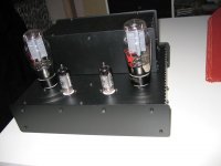
This is the best amp I´ve ever built, no question.
Direct coupling to a choke loaded driver stage is definitely the way to go!
This is my second "Free lunch", the first one used much cheaper iron and IDHT´s and even that one sounded great.
Search also for DRD, Direct Reactance Drive, that´s the same topology.
Direct coupling to a choke loaded driver stage is definitely the way to go!
This is my second "Free lunch", the first one used much cheaper iron and IDHT´s and even that one sounded great.
Search also for DRD, Direct Reactance Drive, that´s the same topology.
Most useful information, thanks alot. Your search tip turned up alot of information that previously has slipped me by, I have alot more background info to work on now. This looks more and more like a really interresting topology, I'm pretty sure this is the trick for my next mod.. I need a higher voltage power supply though.. Tell me, do you use ultrapath cap or conventional cathode bypass? I did read an article (linked below) about very poor immunity against B+ ripple in "conventional ultrapath".. not sure wich route to take. I'm not really worried about hum though, The 71A output tube is low mu, and is followed by a 17.67:1 step down in the OPT.. That should significantly step down any potential hum too.. What do you think about the matter?
"Ultrapath Line Stage"
http://www.geocities.com/dmitrynizh/Ultrapath.htm
"Ultrapath Line Stage"
http://www.geocities.com/dmitrynizh/Ultrapath.htm
Tell me about it. I fell asleep yesterday staring at the amp in the audio rack puzzled by how I was supposed to fit those oil caps. No room on top, no space inside.. Pretty easy mathematics  I think I'll go for the cathode bypass cap too, for the same reason as you. I'll leave the ultrapath for a later tweak, when the amp is ready to move into a new box. What bypass caps are you using? Tried Black Gate VK?
I think I'll go for the cathode bypass cap too, for the same reason as you. I'll leave the ultrapath for a later tweak, when the amp is ready to move into a new box. What bypass caps are you using? Tried Black Gate VK?I put down some thoughts on paper here, feel free to comment them. I went a little bananas saving on the PSU chokes, they have very high DCR but are in fact rated for ample power as I only draw 20mA (that is, unless I upgrade to another power tube). PSU capacitors will be cheap Solen PP or oil bargains on eBay, I was thinking I'd make AE wind the power trannies as I couldn't find any 350-0-350 xformer that also had a 4V winding. There is a hammond with a 5V winding though, I suppose it wouldn't hurt sound quality reducing it to 4V using drop resistors one in each end? Filaments are battery powered, all resistors aren't calculated yet but they are pieces of cake I just didn't bother. The supply itself is modelled in Duncan's excellent PSU designer. I put a 5mA dropper resistor in there to discharge capacitors as a cheap health insurance..
Any thoughts on the scheme?
Any thoughts on the scheme?
Attachments
Rocky - looks kosher, I think you can't go wrong with any of those sketches. You're basically going through what I went through as I developed the Free Lunch originally - starting with a basic amp and then making some bigger changes bit by bit. Should provide a lot of fun!
-j
-j
Jeremy, what a pleasant surprise. Thank you for your kind words, I am a little worried though, about bias points floating around. I am using old DHTs, and as a result I can’t get 100% matched pairs – tube to tube variations can differ quite a bit. My main challenge now will be in the cathode circuit of the output tube – to find some sort of potmeter adjustment that will allow me to set operating points for both tubes with reasonable ease.
Say I connect the dropper resistor (in series with choke) in the ”free lunch” arrangement to the wiper of a pot from 71A cathode towards ground – when I change the 12A plate/71A grid voltage with the pot, I will also at the same time change the cathode voltage of the 71A, as all current goes through the first section of the pot to the wiper, while only current not used by the driver goes from wiper to the pots ground side.. Same with a variable resistor connected to ground in the cathode circuit, designed to adjust 71A cathode voltage: It will ofcourse change the driver 12A plate/71A grid as well.. Even making the dropper resistor in series with the choke variable would affect cathode voltage of the 71A as less/more current passes through it...
Since all adjustments seem to affect other parts of the circuit, I need to think carefully through an arrangement that will allow me to reach desired operating points, yet staying within limits of what the tubes can handle so I won’t blow anything while adjusting.
I would be very curios whether you use potmeter adjustments in your free lunch, or simply get 100% spec’ed tubes and use fixed resistors?
lndm said:One thought on ditching the bypass caps may be along the lines of LED biasing.
With the need for a high voltage at that point you might look at neon VR tubes (or zeners).
Those are nice ideas, and could perhaps be put to good use in the circuit, but I really need to figure out the basic approach in the cathode circuit first, before trying more unconventional stuff.
I'll remember it for later
Following this with BIG interessting.My main challenge now will be in the cathode circuit of the output tube – to find some sort of potmeter adjustment that will allow me to set operating points for both tubes with reasonable ease.
I would be very curious whether you use potmeter adjustments in your free lunch, or simply get 100% spec’ed tubes and use fixed resistors?
I found that well-matched tubes generally settled at very similar voltages - 2% or 3% varaiation, so that was the approach I took. None of the resistors in mine are adjustable. I was able to get a big batch of 6C45P and well-matched 2A3 pairs - I understand that you have a different situation. My advice would be try it first with fixed resistors and see what you get - you might get a pleasant surprise.
As you say, each resistor affects everything else, so adjustment is a little tricky. I would start with making the resistor in series with the plate choke adjustable as this seems to have the most effect, also because the resistor in the output tube's cathode has to be very high wattage, so it is impractical to make this a pot. Instead you would have to get one of those big ceramic adjustable resistors which you adjust by moving a contact and screwing it down - do you know the type I mean? They are expensive!
-j
J Epstein said:
I would start with making the resistor in series with the plate choke adjustable as this seems to have the most effect, also because the resistor in the output tube's cathode has to be very high wattage, so it is impractical to make this a pot. I'll go for adjustable dropper resistor and some big wattage pot arrangement in the cathode network.
Me and my calculator just found that out
 A thought could perhaps be a CCS circuit, Like a Pimm CCS, made adjustable by a pot.. But on the other hand, I think I'll make it resistive for now. There will be potmeter on the dropper resistor, and some high wattage ones in the cathode circuit..
J Epstein said:
Instead you would have to get one of those big ceramic adjustable resistors which you adjust by moving a contact and screwing it down - do you know the type I mean? They are expensive!
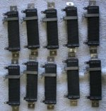
I've found lots of 6K/50W pots (army surplus) of the type you mention (?) for relatively cheap.. Still need to crunch some numbers but I think those will be just great.
Attachments
Rocky said:Since all adjustments seem to affect other parts of the circuit, I need to think carefully through an arrangement that will allow me to reach desired operating points, yet staying within limits of what the tubes can handle so I won’t blow anything while adjusting.
One safety thing you might consider just to get the DC bias points close, is to use a resistor in the B+ to the OPT and maybe to the interstage. You could calculate the value so that if current goes too high, the voltage drops and power dissipation is not grossly exceeded. This is frequently done in the power rails when setting up bias is SS amps. Once you are close, the resistors are removed and final adjustments made. Of course, tubes are not so sensitive to short term overpowered conditions as transistors, but with hard to get tubes I don't see why it wouldn't provide the same protection. Of course, this approach would be much more useful for fixed bias, as your cathode resistor already provides more or less the same function.
Sheldon
Those resistors would likely be connected by switches in my amp, I think I hear what you are saying, Sheldon.. But I didn't quite get how you're intending the resistor to the B+ side of the choke (right?) to work (and - wouldn't a resistor on the OPT and the drop it causes completely mess up my bias adjustments?). I'll be listening very carefully if you'd take the time to elaborate in greater detail..
- Status
- This old topic is closed. If you want to reopen this topic, contact a moderator using the "Report Post" button.
- Home
- Amplifiers
- Tubes / Valves
- a directly heated monkey?