Well Rocky, on further reflection it was a half baked idea in this instance. With transistor amps, particularly AB amps, the voltages are low and bias currents low, but the bias current could potentially go very high. With a relatively small resistor in the supply line - even a few ohms, as the current goes up, the voltage goes down and the transistor dissapation remains within safe limits. With a 5 ohm resistor and 30V rails, as the current goes from 100mA to 5 amps, the rail voltage to the transistor goes from 29.5 V to 5 V, and the dissipation for the transistor is only 25 watts, instead of what would have been 150 watts. Of course, the resistor must be removed for operation, but it's cheap insurance for set-up.
I thought of it initially, because I have a resistively loaded DHT amp which is then connected to the OPT via a para feed type cap arrangement. I was concerned about faults which could cook the output tubes, but realized with the resistive loading, I couldn't exceed the tube rating if I wanted to. In your case I think the required fixed resistor to provide protection would require too much voltage drop to be of much use in testing the circuit near it's final operating point. So maybe a related approach would be in order. If you've got some of those big fat adjustable's, you could put one in the B+ for testing purposes and increase the B+ stepwise as you sneak up on your endpoint. Would give you peace of mind and catch any gross errors well before you cooked a tube.
Sheldon
I've been drawing sketches, scratching my head, and growing grey hairs all day, and I think that, for now, I have come to the conclusion to make it without safety measures, and relatively small margins of adjustment, perhaps in the order of 80%-110% emission from both tubes. I will keep this in mind though, I've been thinking of different was to bias the tubes individually switching them together when voltages are right, but I have not come across any eureka solution yet. It'll rest in the back of my mind, but to anyone on the forum; please speak up if you have any clever idea on the matter!
-Not sleeping just thinking with my eyes closed listening to beautiful music
If you ever thought Morten Harket (A-ha) sings like an angel, you should hear him on milli-watt DHT amplifier and TAD4001-equipped tractrix horns, late night when no cars or screaming babies in the neighbourhood disturbs This is getting more and more addictive, and I must say DHTs are definitly a step up even though I have added an extra stage. In my honest opinion far better than single tube 6s45pi or similar high-mu-IDHT tubes loaded with the same output iron. Sound is just magical, the only downside is it keeps me up at night
12A and 71A is definitly a perfect couple. I can't wait to get them directly coupled to each other
-Not sleeping just thinking with my eyes closed listening to beautiful music
If you ever thought Morten Harket (A-ha) sings like an angel, you should hear him on milli-watt DHT amplifier and TAD4001-equipped tractrix horns, late night when no cars or screaming babies in the neighbourhood disturbs
12A and 71A is definitly a perfect couple. I can't wait to get them directly coupled to each other

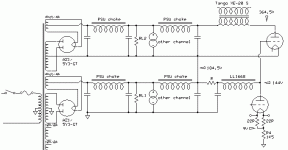
I had this crazy idea that I think might work. It is nothing like the free lunch or monkey, but something quite different. Two powersupplies one on top of the other, taking care of the biasing easy as pie.. Or so it seems. Could anyone confirm wether this actually will work and what the downsides of this topology might be?
see attached sketch...
see attached sketch...
Attachments
Fuling said:Just make really sure you get the startup sequence right with all those direct heated tubes and rectifiers!!
This is new ground to me.. I have an idea on an idiot-proof approach though - a buffered ("timer controlled") relay switch that switches in the tubes for load resistors after for example a second.. eller hur?
[ Could anyone confirm wether this actually will work and what the downsides of this topology might be?
stacking PS has been done successfully before.
See
http://f5.grp.yahoofs.com/v1/wGhWRM...rw2xQloWe2gQy4ZPySg/75TL DC coupled GM100.pdf
http://www.chimeralabs.com/images/axiom.sch.jpg
Thanks for the links agent5. It calms me to see. I haven't seen it used before, and since the idea is very simple I thought it may exist a good reason why noone used it. So thanks again.
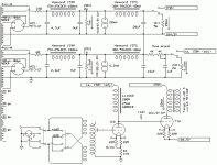
Sounds good. the switch on the driver tube will be omitted at is has no use (the driver will self bias) and thou it will present both cathode and grid voltage to the output tube, nothing bad will happen unless there are power on the 71A plate, as I get it. So the only trick I need to implement is to present the B+ to the 71A with a delay, wouldn't you agree?
Fuling said:If you solve the startup issues this should work very good.
Sounds good. the switch on the driver tube will be omitted at is has no use (the driver will self bias) and thou it will present both cathode and grid voltage to the output tube, nothing bad will happen unless there are power on the 71A plate, as I get it. So the only trick I need to implement is to present the B+ to the 71A with a delay, wouldn't you agree?
Rocky said:Thanks for the links agent5. It calms me to see. I haven't seen it used before, and since the idea is very simple I thought it may exist a good reason why noone used it. So thanks again.
Here's another one: http://www.valvediy.com/simplexpg7.html
Rocky said:Sounds good. the switch on the driver tube will be omitted at is has no use (the driver will self bias) and thou it will present both cathode and grid voltage to the output tube, nothing bad will happen unless there are power on the 71A plate, as I get it. So the only trick I need to implement is to present the B+ to the 71A with a delay, wouldn't you agree?
A IDHT rectifier on the 71A would do the trick, unless you want DHT throughout.
Sheldon
Sheldon said:
A IDHT rectifier on the 71A would do the trick, unless you want DHT throughout.
I'm not dead set on DHT rectifiers although I like the AZ1 much better than say GZ34 (I have som black based Mullards I've been fiddeling a bit with).. But I'm not sure I follow you, how would an IDHT rectifier in the 71A supply make life easier? (perhaps a silly question
 )
)Rocky said:
I'm not dead set on DHT rectifiers although I like the AZ1 much better than say GZ34 (I have som black based Mullards I've been fiddeling a bit with).. But I'm not sure I follow you, how would an IDHT rectifier in the 71A supply make life easier? (perhaps a silly question)
I'm not sure I've got it right, so let me lay out the sequence as I see it, and as I understand the circuit (warning: can't be assumed that I do understand). With IDH rectifier on the output (top) of the power supply and DH rectifier on the driver B+ (bottom), the bottom supply would come on at about the same time as the driver tube. Since this tube is self biased, as you say, no problem. At this point the output tube filament is powered up, but the top supply is not yet on, as the IDH takes several seconds to power up. So you have 180V on the cathode of the OP tube and 140 on the grid - good. Then the top supply comes up over the next couple of seconds. Should be completely safe.
Sheldon
In case of both DHT rectifiers, Won't both supplies trigger at the same time, only the top supply rises twice as fast because of the DC bias from the bottom supply? So when the bottom supply is stabilized, so is the top supply (assuming identical supply responses from both supplies)?
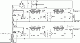
I've attached a new PSU sketch that should provide a relay delay in the DHT PSU circuit. Probably doesn't cost me anything to get a spare winding for it and parts cost will be low as no high grade components will be needed..I'd really like to use the AZ1 rectifiers for both supplies.. I think I understood that Fuling had some bad experiences with such circuits though, what can go wrong with these circuits except for tolerances in the electrolytics affecting switch-on time?
I've attached a new PSU sketch that should provide a relay delay in the DHT PSU circuit. Probably doesn't cost me anything to get a spare winding for it and parts cost will be low as no high grade components will be needed..I'd really like to use the AZ1 rectifiers for both supplies.. I think I understood that Fuling had some bad experiences with such circuits though, what can go wrong with these circuits except for tolerances in the electrolytics affecting switch-on time?
Attachments
Rocky said:what can go wrong with these circuits except for tolerances in the electrolytics affecting switch-on time?
Hmm.. answering my own question here, I suppose the mosfet can go toast in an open position. So I will have to use a MOSFET that will not toast..
Rocky said:In case of both DHT rectifiers, Won't both supplies trigger at the same time, only the top supply rises twice as fast because of the DC bias from the bottom supply? So when the bottom supply is stabilized, so is the top supply (assuming identical supply responses from both supplies)?
I've attached a new PSU sketch that should provide a relay delay in the DHT PSU circuit. Probably doesn't cost me anything to get a spare winding for it and parts cost will be low as no high grade components will be needed..I'd really like to use the AZ1 rectifiers for both supplies.. I think I understood that Fuling had some bad experiences with such circuits though, what can go wrong with these circuits except for tolerances in the electrolytics affecting switch-on time?
Yes, to the question of supply timing with DH rectifiers. Actually, the turn on time is so short that I really doubt that there is any significant issue with over biasing the tubes during turn on. If there is a current spike it will be short and tubes, unlike transistors, can tolerate brief out of range conditions. A much more significant concern would be if your bottom rectifier or driver tube fails or suffers a faulty connection with the socket then you definitely risk the output tube. So maybe the way to protect against all of this is a current sensing circuit on the output cathode, that would open the top B+ if the current went beyond a certain point? Would only need a volt or so to activate a transistor gate. This is all spoken with no direct experience. SY, words of wisdom needed here.
Sheldon
Sheldon said:
So maybe the way to protect against all of this is a current sensing circuit on the output cathode, that would open the top B+ if the current went beyond a certain point?
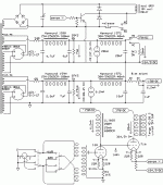
Clever idea. Not exactly sure how to design it though. I'd have to use something like a 12V supply with ground biased at the bottom of the cathode resistor (bias voltage of upper supply), with a transistor sensing the top of that cathode resistor, turning the relay on to switch over to the load resistor if the voltage indicates a current over say 25-30mA..?
EDIT: My immidiate thoughts would be a comparator comparing that 1V to an adjustable resistive divider of the 12V supply, feeding a transistor buffer driving the relay...
A possible approach.. Using a dual SPDT relay this circuit uses one relay section to lock the relay in a closed position, to avoid the circuit switching back on once it has disconnected the B+. The B+ can be put back manually by releasing a switch. How does it look?
Attachments
- Status
- This old topic is closed. If you want to reopen this topic, contact a moderator using the "Report Post" button.
- Home
- Amplifiers
- Tubes / Valves
- a directly heated monkey?


