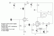
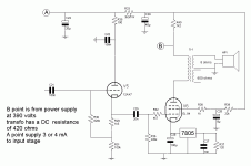
Hi Audiofan,
The circuit as shown will work - for a while. The screen supply is fine as shown.
R40 and C29 are not really required - you could just wire the stuff that goes to that point directly to point B and ditch R40 and C29.
I think you also need to check the bias network for the EL84. with that 120 Ohm resistor around the 7805 I think you will get 5/120 = 41.7 mA
With about 380V across the EL84 then you will have nearly 16 watts anode dissipation - thats too much, it should be less than 12 watts max.
The 120 Ohms needs to be 160 Ohms or there abouts - Use 2 x 82 Ohms in series or 2 x 330 Ohms in parallel instead of the 120 Ohm.
This was just a quick look BUT hope its helpful.
Cheers,
Ian
Your answer is very usefull , the point I have trouble with is screen voltage
I estimate R37 at 42 mA
ground pin of 7805 at 3mA
cathode at 45 mA
screen at 5 ma ( almost a wid gest )
Plate at 40 mA
voltage drop across tranfo 17 volts
plate at 373 volts
screen at 267 volts
Is this screen voltage 100 volts below plate voltage OK ?
The tube is a 6l6gc and from RCA rc-30 book maximum plate dissipation is 30 watts or 19 watts for a regular 6L6 , I expect to use it " cold "
An EL34 is a smaller tube with a maximum plate dissipation of 12 watts, a lot smaller...
Your Screen Current guess is about right.
Having screen voltage 100V below the anode is fairly typical operating point for 6L6 and is fine. Once built and running you can experiment with R39 if you want - try say 15K or even 10K. Lower value should give you a little more power BUT a bit less compression.
I missed that you were using 6L6 instead of EL84 shown on the schematic. The 7805 bias network with 120 Ohms will be just fine for 6L6 - instead I would then worry about R36, this is too high for 6L6, recommended maximum for 6L6 in autobias is 250K. Change R36 to 220K or 270K.
If the intended use is for a guitar practice amp then I would also drop the value of C25 to 10nF to give low frequency roll off -3dB point at 72 Hz (with 220K for R36). That should stop the amp getting too "muddy" in the bass.
Cheers,
Ian
I would say your R39 is too big ...You are relying on this R39 for your DC voltage drop.... WIth concern to AC signal it is a -20dB/ Decade filter slope...although the 120Hz ripple voltage attenuation is a bit under -40dB... your concern would be ripple current at lowest audio frequencies and it's effect on the Screen voltage modulation...this would create sever non-linearities...maybe this is good for guitar amp... I suggest for linearity to regulate the screen voltage..or use a different arrangement in the Screen, possibly a LC ... If you want the RC arrangement, you may need to increase C28 for "hold-up" considerations....you can taylor this by ear, if it is for guitar amp..
Chris
Chris
So I made modifications:
R36 at 220k for cerrect voltage at grid of 6L6GC
C25 at 20n for a 3 db point frequency at 36 Hz ( so amp could be used for bass guitar )
Thank to Gingertube for the advice
Around sreen circuit and Cerrem advice
In my stockroom I have 8 uf not 4 uf so I change C28 to 8 uf
the filter R39 & C28 is perfect for ripple rejection
Audio AC signal will flow from screen, R 38 and C28, at 40 Hz reactance of C28 is 500 ohms and R38+C28 give an impedance of 1.1 K ohms
For 5 watts in 8 ohms speaker I will have
6.3 volts RMS at speaker
0.79 amp RMS in speaker
152 volt RMS at plate of tube
33mA RMS in plate circuit
transformer ratio 24:1
In screen ( wild guess ) 4 mA RMS, so in 1.1 K ohms circuit about 4.5 volts RMS of swing at screen.
Same type of maths gives 1.3 volts RMS swing at cathode.
I think it should work quite well.
Attachments
- Status
- This old topic is closed. If you want to reopen this topic, contact a moderator using the "Report Post" button.

