Hello,
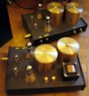
please look at my last aplifier,
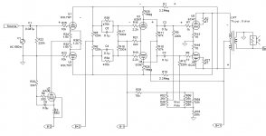
sounds very good, but I got a feeling that it starts to distoring the sound too fast. I believe that its potential is greater, I built identical similar one before.
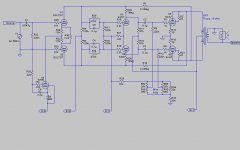
I attached measured voltages.
could you give me some advice hoe to made some regulations to improve the power?
please look at my last aplifier,
sounds very good, but I got a feeling that it starts to distoring the sound too fast. I believe that its potential is greater, I built identical similar one before.
I attached measured voltages.
could you give me some advice hoe to made some regulations to improve the power?
Attachments
Hi, padamiecki.
Some thoughts on how I would improve the amp circuit:
* Reduce the input grid resistor to 100k, to minimise the Miller capacitance, which could attenuate the higher frequencies.
* Add a 10k grid stopper resistor, between the input tube grid and the grid resistor, to prevent parasitic oscillations from occurring; this needs to be very close to the grid pin to be effective.
* Change the ECC83 to a long-tail pair splitter, instead of the paraphase you have now. This will give you superior blance and lower distortion. Use a solid-state constant current sink (CCS) in the tail of the splitter (i.e. in place of R25) and add a 470 ohm resistor in the cathode of each half of the ECC83, i.e. between each cathode and the CCS, to give some current feedback and to improve DC balance, since you have DC coupling to the ECC82
* For the CCS, you need a low negative voltage supply. If you have an existing separate winding of around 12v to 30v on your power transformer, which you could use for this purpose, it would be the best solution. If not, you could probably achieve it with a voltage doubler from the 6.3v heater supply but you would must disconnect the existing heater circuit from ground, so that it is grounded only via the positive end of the voltage doubler.
* Change the ECC82 to a differential amplifier instead of cathode follower (CF). There is no need to use a CF to feed the EL4s and the differential arrangement will give more gain. Use plate load resistors of around 33k, 2W and a tail resitor of 27k, 5w. Also, add 1Meg feedback resistors between the plates of the ECC82 and ECC83, which will improve balance and distortion still further.
* Bypass the cathode resistors of the EL34s (R30 and R31) with 470uF 50v capacitors, which will improve gain and available power.
* Finally, if you find that the overall gain is more than you require, you can reduce it by adding feedback resistors (say, 2.2Meg) cross-coupled between the plates of the EL34s and ECC83 (this has to be cross-coupled for the feedback to be negative). You can experiment with different values of feedback resistors to obtain the gain, damping and sound quality that you need.
Wouah,
Full balanced feedback both for the whole amp and another in the push pull cathodes !
Check for possible parasitics with such scheme !
Just a question, why do not use a commun cathode resistor at the secondary CT for the EL34 ?
Quick looking, this seems increase the PP internal impedance and degrades damping factor.
Yves
Yes, you're right about the need to get rid of the current NFB in the PP pair but a common bias resistor would be unsuitable for class AB1. I suggested bypassing the existing resistors instead to improve the application of self-bias.Just a question, why do not use a commun cathode resistor at the secondary CT for the EL34 ? Quick looking, this seems increase the PP internal impedance and degrades damping factor.
Better still, though, would be to change to fixed bias, which would provide control over the quiescent current and make it possible to get more power. This would require a negative supply of at least -45v and a couple of pots to adjust and balance the OP tube currents.
Thank you all for your comments,
they were much appreciated
? I thought that paraphase introduced local feedback and gives this stage more linear?
Next time I will try to update the schematic with your comments.
well, when designed I would minimise gain to get full power on maximum pot setting. I am afraid that after resigned fro CF I will get too much gain and will have to use more nfb, which I would not to do.
Similar thing is with use decoupling cathode resistors. I would not use them.
Anyway all of your comments were very interesting, tommorow I will send updated schematic
")
they were much appreciated
ray_moth said:Hi, padamiecki.
* Change the ECC83 to a long-tail pair splitter, instead of the paraphase you have now. This will give you superior blance and lower distortion. Use a solid-state constant current sink (CCS) in the tail of the splitter (i.e. in place of R25) and add a 470 ohm resistor in the cathode of each half of the ECC83, i.e. between each cathode and the CCS, to give some current feedback and to improve DC balance, since you have DC coupling to the ECC82
? I thought that paraphase introduced local feedback and gives this stage more linear?
Next time I will try to update the schematic with your comments.
ray_moth said:* Change the ECC82 to a differential amplifier instead of cathode follower (CF). There is no need to use a CF to feed the EL4s and the differential arrangement will give more gain. Use plate load resistors of around 33k, 2W and a tail resitor of 27k, 5w. Also, add 1Meg feedback resistors between the plates of the ECC82 and ECC83, which will improve balance and distortion still further.
* Bypass the cathode resistors of the EL34s (R30 and R31) with 470uF 50v capacitors, which will improve gain and available power.
* Finally, if you find that the overall gain is more than you require, you can reduce it by adding feedback resistors (say, 2.2Meg) cross-coupled between the plates of the EL34s and ECC83 (this has to be cross-coupled for the feedback to be negative). You can experiment with different values of feedback resistors to obtain the gain, damping and sound quality that you need.
well, when designed I would minimise gain to get full power on maximum pot setting. I am afraid that after resigned fro CF I will get too much gain and will have to use more nfb, which I would not to do.
Similar thing is with use decoupling cathode resistors. I would not use them.
Anyway all of your comments were very interesting, tommorow I will send updated schematic
well, it looks more complex...
... but should work!
Ray_Moth, could you please check if feedback loops are right? I changed the values proposed by you.
Anyway from simple schematic it became hard to pass like the maze!
I would like to point once again that schematic in the first post is working, and the sound is excellent, with very deep scene.
But who knows, if this last proposition is possible to build, maybe I will try?
Attachments
Re: well, it looks more complex...
My preference goes to the first one
With just a question !
I do like the CF to isolates the phase splitter from the power stage, but why are stoppers in the EL34 grids so large ?
Yves.
Here is my new born babe !
padamiecki said:... but should work!
Ray_Moth, could you please check if feedback loops are right? I changed the values proposed by you.
Anyway from simple schematic it became hard to pass like the maze!
I would like to point once again that schematic in the first post is working, and the sound is excellent, with very deep scene.
But who knows, if this last proposition is possible to build, maybe I will try?
My preference goes to the first one
With just a question !
I do like the CF to isolates the phase splitter from the power stage, but why are stoppers in the EL34 grids so large ?
Yves.
Here is my new born babe !
Attachments
why are stoppers in the EL34 grids so large ?
4k7 is large?
In UL, the input capacitance will be something like 40pF, maybe a bit less. 4k7 feeding 40pF creates a pole at around 850kHz, easily a decade higher than the output transformer, but low enough to be suppressing oscillation. It's a pretty reasonable choice, I think.
Ray_Moth, could you please check if feedback loops are right? I changed the values proposed by you.
No, padamiecki, I'm sorry, what you have drawn is not what I suggested.
Firstly, the ECC82 plates are connected through their load resistors to the plates of the EL34s. That's a well-known form of local feedback ("partial" feedback) across the EL34s but is unnecessary IMO because you already have cathode feedback both through the separate unbypassed EL34 cathode bias resistors, which you have retained, and also through the cathodes being connected to the OP secondary, the mid-point of which is grounded. You will not have enough B+ to get sufficient swing with the arrangement you have drawn.
Secondly, you have done the same thing with the plate loads of the ECC83 and that will give you positive feedback because it's not cross-coupled.
Rather than try to explain my ideas verbally any further, which is difficult and likely to be confusing, let me show you the circuit I use for my own amp. It's based on the same principles I am suggesting but uses a 6SL7 instead of your ECC83, a pentode CCS instead of SS, 6SN7 instead of ECC82 and triode-connected EL34s with fixed bias. Please see attached:
Attachments
Just a few more comments:
6CA7 is the equivalent of EL34; I only used it in this schematic because it's a Spice simulation model (using LTSpice) and my model for that tube is called 6CA7.
I use a step network, instead of direct coupling, between the first and second stages, because it gives me easier operating points to work with and is less sensitive to imbalance between the two halves of the double triodes. It provides sufficient stability for the long cross-coupled feedback loop, which direct coupling would also do of course.
Re: Re: well, it looks more complex...
very very fine!
but the global nfb exists, which IMO spoils the depth of the stage.
About a grid stopper answered SY.
Yvesm said:Here is my new born babe !
very very fine!
but the global nfb exists, which IMO spoils the depth of the stage.
About a grid stopper answered SY.
ray_moth said:No, padamiecki, I'm sorry, what you have drawn is not what I suggested.


this was my ask to check if the feedback are correct.ray_moth said:you have done the same thing with the plate loads of the ECC83 and that will give you positive feedback because it's not cross-coupled.
looks very promisive, I am sure that sounds perfect!ray_moth said:... let me show you the circuit I use for my own amp. It's based on the same principles I am suggesting but uses a 6SL7 instead of your ECC83, a pentode CCS instead of SS, 6SN7 instead of ECC82 and triode-connected EL34s with fixed bias. Please see attached:.
Why do you prefer 6SL7 instead ECC83 as voltage stage? Because of higher transconductance or linearity?
ray_moth said:I use a step network, instead of direct coupling, between the first and second stages ...
anyway, if you would ommit C1, you will get only 1 capacitor in signal path, that would be cheaper and probably better sounding.
Why do you use high-pass filters during coupling to the second stage?
When I decided to build an EL34 amp, I decided to use all octal based tubes. This decision was based on the opinions of several people that 6SL7 and 6SN7 are more linear than ECC83 and ECC82.Why do you prefer 6SL7 instead ECC83 as voltage stage? Because of higher transconductance or linearity?
I'm sure you're right (although the difference would not be great) but, when I tried that, I found that my 6SL7s were not well balanced, leading to a DC offset which became quite large when amplified by the 6SN7. In addition, the voltage on the grids of the 6SN7 were too high. The step network avoids both of these problems.anyway, if you would ommit C1, you will get only 1 capacitor in signal path, that would be cheaper and probably better sounding.
That's not its purpose - you're referring to the step network, which I addressed above.Why do you use high-pass filters during coupling to the second stage?
This decision was based on the opinions of several people that 6SL7 and 6SN7 are more linear than ECC83 and ECC82.
They are indeed. But... the 6SL7 has no better linearity than the ECC81/12AT7. And that's no slam against the 6SL7 since the 12AT7 can be quite impressive.
SY said:“Reality is a mistake, we must rectify it.”
 is this about spirit, current, or alcohol?
ray_moth said:Please see attached:
Dear Ray_Moth
after careful studying your circout I can see a positive feedback between second stage and output tube: (upper part) R1 - R28 - C2 - U5 - transformer - R1. Upper pin R28 meeth the same feedback signal in phase, like bottom pin R28...
Please see attached scan of signal feedback phases,
Why am I wrong?
Attachments
- Status
- This old topic is closed. If you want to reopen this topic, contact a moderator using the "Report Post" button.
- Home
- Amplifiers
- Tubes / Valves
- my last project