http://www.tubes.mynetcologne.de/roehren/el34set/el34set_e.html
Hey, I need some advice on this schematic. Found it here a couple months ago and getting ready to build it. I'm no engineer, just a solder slinger. The thing that intrigued me was the highish B+ and 10k OPT primary. I tried to do a load line but got totally confused . I originally looked at el34 SET designs because I have everything to build one except the OPT's. I was thinking of having some wound for this that would be a little beefier than the se125's he used. I also have a drawing that I did for a power supply to substitute, it would be way more mA than required and I would have to bring the voltage down some, but once again it's stuff thats been laying around that I need to do something with. I'm planning on running this through some Heresy 2's with a CD straight in(Marantz 50 with variable output). I know there are some really good tube guys on this forum and if any of you could see your way clear to help out a fellow tube nut and maybe save me some headaches and heartaches on this one I would be very grateful.
Hey, I need some advice on this schematic. Found it here a couple months ago and getting ready to build it. I'm no engineer, just a solder slinger. The thing that intrigued me was the highish B+ and 10k OPT primary. I tried to do a load line but got totally confused
. I originally looked at el34 SET designs because I have everything to build one except the OPT's. I was thinking of having some wound for this that would be a little beefier than the se125's he used. I also have a drawing that I did for a power supply to substitute, it would be way more mA than required and I would have to bring the voltage down some, but once again it's stuff thats been laying around that I need to do something with. I'm planning on running this through some Heresy 2's with a CD straight in(Marantz 50 with variable output). I know there are some really good tube guys on this forum and if any of you could see your way clear to help out a fellow tube nut and maybe save me some headaches and heartaches on this one I would be very grateful.Attachments
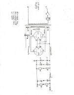
For a SE EL34 this power supply is a little overkill but will work just fine. The current drawn by the two EL34s would probably only require a single 5U4, and this would lower your B+ a bit too.
The caps would need the equalising resistors connected across them, i.e. joined to the junction in the middle. Also you could easily get away with just the one pair of 47uF in series for the first cap.
The choke should be whatever you can get, around 5-10H and rated for 1.5x the current should work ok.
The second cap can be whatever you want, 100uF total would be ok. You probably don't need to use series caps here, but I am guessing this is what you have.
To model your power supply, go to duncanamps.com and download the power supply designer (and the tube database!) and plug in the numbers, and adjust to get the smoothest curves.
Good luck!
jaymanaa said:
Yeah, that is from my homepage
")
If you are open to experimentation, I would suggest to try even higher voltage, up to 450V (plate to cathode) for the output stage (while staying within total Pd limits, of course). For Ra, don´t go lower than 10k.
Don´t get fooled by old spec sheets, suggesting lower voltages, higher currents and lower Ra - the objectives were quite different back then (get the most power out of it while using the least iron/copper mass at the same time).
This circuit as shown does magic on voices, choirs, small Jazz combos, chamber music and the like. As I wrote, this one was built to do exactly this. It certainly is no "rocker", though, as a quite similar circuit from the Angela homepage does suggest.
As a side note, this circuit was the first one I really was able to distinguish between different 6SL7 types / brands in blind tests. I wouldn´t have believed until then. A more obtanium alternative to the JAN CHS Sylvania 6SL7 is the cheap and plenty Reflektor 6H9C (6N9S), which sounds better (in this circuit) than many other much more expensive NOS 6SL7 brands, except those old Sylvanias.
Comparatively, the influence of EL34 brand choice is much less audible.
Tom
Thanks for the input, I was thinking I could get by with one 5u4, but not really knowing, thought I would error on the side of caution. One will be much handier as the chassis layout is a little crowded. Good point about equalising resistors too. I may use 600v caps as well. I have a bad habit, that if I'm not sure about the designing of something, I just use overkill. I need to work on that. I'm just more at ease with a soldering iron than a pencil . Hey tubes4e4, It surely is a small world (thanks to the internet). I have many questions. Let me start by saying I really like your circuit (and home page). Very nicely done, and so good of you to share it. You use the term (chamber music). I'm not sure what you mean? I listen to bluegrass and folk, which is all string instruments (no percussion or piano), and for the most part female voice. The one thing I guess that concerns me, is this kind of music uses a very large Bass fiddle instead of drums to keep time. What is your opinion on the low bass capabilities of this circuit? Next, I am curious if you ever experimented with a 6SN7 in place of the 6SL7? I only ask because I have several about. Thank you both again, and please check back from time to time as I am sure I will be needing more advice as this project moves along. I plan to start on the layout this weekend. Jay
. Hey tubes4e4, It surely is a small world (thanks to the internet). I have many questions. Let me start by saying I really like your circuit (and home page). Very nicely done, and so good of you to share it. You use the term (chamber music). I'm not sure what you mean? I listen to bluegrass and folk, which is all string instruments (no percussion or piano), and for the most part female voice. The one thing I guess that concerns me, is this kind of music uses a very large Bass fiddle instead of drums to keep time. What is your opinion on the low bass capabilities of this circuit? Next, I am curious if you ever experimented with a 6SN7 in place of the 6SL7? I only ask because I have several about. Thank you both again, and please check back from time to time as I am sure I will be needing more advice as this project moves along. I plan to start on the layout this weekend. JayWell, I built the power supply and ended up with 430vdc (no load, but I'm not expecting much sag from this 13# transformer). I also picked up a couple of NOS RCA 6SL7GT's. I'm now getting ready to order the OPT's from Heyboer. I'm specing 10K pri., 120 mA, 15 watts, 4-40khz. (any thoughts before I pull the trigger?). The only thing I'm having trouble finding is the copper to build the chassis. I'm thinking I want 16guage. Anybody know a place to buy sheet copper online? I'm just a little concerned about how the bass response will be if anyone has any thoughts. Thanks, Jay
Thanks, Jay Thanks In Advance, Jay
lndm said:The difference in conductivity for copper and aluminium is not huge and a chassis is often made from a big slab of it. Aluminium may give fewer corrosion issues.
Thanks, I've pretty much given up on copper for this one. I do have a source for aluminum, however I came across a piece of scrap stainless at work today that is allready bent and welded just a hair larger than I was shooting for. Would stainless be a good enough conductor or would I want to add a copper buss?
lndm said:Steel is not as good a conductor as copper or aluminium, and by a larger margin. Magnetic fields would also permeate the steel and spread and induce eddy currents (I think). Not sure how successful this would be.
Good point. I think I'll go with aluminum. Sorry for all the goofy questions but this is my first amp and I don't want to muck it up too bad if I can help it. Do you have any thoughts or opinions on the schematic as far as bass response? My wife tells me that chamber music doesn't have much going on in the way of bass. I'm hoping that the extra bucks for the OPT's may pay off in the long run.
jaymanaa said:bass response?.... extra bucks for the OPT's
Can't argue with this.
Well this is going to be an amp someday I hope. One question I have is with all my 6.3v heaters connected I have 7.38 volts. This transformer ran more heaters in it's previous life and probably had some sag that is now non-existent. What if I were to rectify the 6.3 with a simple diode bridge? Wouldn't that give me a little drop, and isn't DC more desirable for the heaters? Any thoughts and ideas would be appreciated. I think I am learning from this project after sort of hitting a wall with the books. Thanks, Jay
Attachments

Awesome.
Just my opinion but the extra voltage will allow you to use a series resistance. The resistance of a cold heater is low and when hot it is high. Therefore the resistor will have most effect when the heaters are cold. It will reduce the inrush current and prolong the life of the heaters.
AFAIK, AC on the heaters is an excellent choice due to the simplicity of the circuitry, except for the issue of hum. I use AC and have no significant hum (except in my phono stage). I actually get more hum from my supply rails (fixed with a few neat tricks).
lndm said:Awesome.
Just my opinion but the extra voltage will allow you to use a series resistance. The resistance of a cold heater is low and when hot it is high. Therefore the resistor will have most effect when the heaters are cold. It will reduce the inrush current and prolong the life of the heaters.
AFAIK, AC on the heaters is an excellent choice due to the simplicity of the circuitry, except for the issue of hum. I use AC and have no significant hum (except in my phono stage). I actually get more hum from my supply rails (fixed with a few neat tricks).
Could you recommend a value and wattage to start with, or maybe there is a formula (I have to remember math is my friend). With 2 el34, and 2 6sl7 heaters I am pulling 3.80 amps at 7.38 volts.
Add the currents for all the heaters. Then, 7.38V - 6.3V leaves 1.08V in excess. 1.08 divided by the total current gives the resistance (0.28 ohms). 1.08 squared, divided by the resistance gives the power dissipated by the resistor (use 5W for example).
In practice, this will only be a starting point and you'll need to tweak.
In practice, this will only be a starting point and you'll need to tweak.
Thanks indm, This is how I learn. By trying to build something and getting guidence along the way. I could read that 100 times in a book and it won't stick. Actually using it to solve a problem seems to make it soak in. I'm going to try and get by the electronics store today as I have very few resistors in the 5 watt range. I will keep you posted. Thanks Again, Jay
That seemed to do the trick and it never hurts to be kind to the tubes with prices what they are for the good ones. I picked up an assortment of 5 watt resistors and tried a .22 first which gave me 6.75 volts. Then I tried a .33 which hit dead on at 6.32v. I picked up a nice piece of aluminum today 1/8 thick and 11" wide by 19" long. I plan on trying to do some layout work tonight. I may mark it all out and post a pic for scrutiny. I plan on having mains and signal at opposite ends and rotating opt's 90 degrees from pt. I will have to look at the sockets to figure out how to keep evrything short and tidy (this may take some time and thought). Is there any problem with putting the choke directly in front of the pt with a 5U4 on each side of it. I have some coke bottle ones and thought it would look good that way. Any ideas are allways welcome, and thanks for the help so far. Jay
Hi Jaymanaa,
A few words from me. Firstly, it is fine to experiment but laudable to ask for advice. A waste of time to re-invent the wheel, and experience is fine, but second-hand is cheaper!
I would also have chosen the alu chassis. Although most commercial amps are built on steel chasses, I often had problems with hum (magnetic induction), even when using the recommended single star-type earth. With alu I could earth all over the place without problems. Well, to qualify, not earth so that the transformer-rectifier-filter capacitors are far apart; those you earth at one point, but I had no problem with lesser-current earths at the most convenient point.
Just as an example, I recently had to re-organise someone's Mullard 510 on a steel chassis (hum) and when all else failed tried to experiment with different power transformers. You would not imagine the difference in "hum induction" I found. Best orientation was often at an angle somewhere in space. In the end I had to rebuild comepletely on an alu chassis to solve the problem.
Then to repeat what was mentioned on other threads, that you need to view the "dc on heaters" with care. Just simply 6+V through a bridge rectifier followed by a large C can cause more harm than good. You can easily get more interference from the "turn-on" current spikes than the original ac would have given. Unless you can smooth the dc to a fair degree, stay with ac. Often the problem is not with the 6V ac as such but with ill conceived wiring. I have used ac heaters even down to pre-amps with phono input without too much trouble (although with regulators etc. available nowadays I would now use a serie heater string with dc for that).
A little more than you wanted for now, but hopefully of useful guidance in future projects.
Regards.
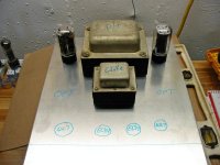
This is a rough Idea of the layout I have in mind. Anyone see any pitfalls or concerns? Anyone ever use "Krinkle paint" for trans. end bells? I don't know how this amp will sound, but it may be in the running for the heaviest 8 watt amp in the world. Thanks for any and all advice, Jay
Attachments
- Status
- This old topic is closed. If you want to reopen this topic, contact a moderator using the "Report Post" button.
- Home
- Amplifiers
- Tubes / Valves
- Will this work?