In response to my PSU capacitors/electrolytics thread, I want to use a hybrid bridge, as recommended by Kevinkr, using a 5R4 tube (as my mains transformer has heater taps for this 5V/2A). I then replace the positive leading diodes with the tube rectifier and reduce the first capacitor values drastically (maybe 10uF only instead of 330uF), correct?
As I need to drop some voltage I was thinking choke or regulation, still open as of this.
For the regulation option I was delighted to find a nice and simple schematic from Headwize by Kevin Gilmore, see attachement. I can't understand how this can use a 450V capacitor after the bridge, can you?
Math=375 +/-10% mains variation * RMS value is 375 x 1,1 x 1.414 = 583V aka a 630 capacitor should be used!
One thread I read that hybrid topology gives different noise spectrum in the positive and negative rectifier cycle? I think it was Geek talking about this...
Also in another schematic by Kevin (see next posting for attachement) he uses a full wave topology instead. Except for diode ratings and such as discribed in textbooks, this should be exactly the same?
Thanks...
Attachments
Hola...
I'm sorry to say I use Windows and cut & paste from Headwize.com
I forgot to mention mission statements for my PSU:
1. Drop some voltage
2. Use bipolar PSU for some faint survival reasons + noise cancelling opportunities...
3. Make a simple regulator to drop voltage before I buy a lot of chokes.....
4. Understand the bugger.....
thanks jeapel, tips noted! 
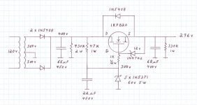
The regulator can be improved a lot, I guess, most likely with a 2 transistor version, like attached.
Also I think I'm being a bit paranoid about using a ss/tube hybrid rectifier and then a SS psu regulator, this is maybe overkill. Point is I just want to check out and build the different topologies.
Also another question that I have regarding seperate mains transformers for positive and negative rails as in attachement... Are there any pro's regarding this?
Attachments
jeapel said:hi
maybe add capacitor on zener for better ripple rejection
and reverse diode protection on power transistor
bye
may I ask what is the logic behind having the 1N5408 between the D and S when the MOSFET already has one internally?
- Status
- This old topic is closed. If you want to reopen this topic, contact a moderator using the "Report Post" button.
- Home
- Amplifiers
- Tubes / Valves
- PSU topology & regulator