I'm currently working on a single ended amp using screen driven 6CD6GA sweep tubes. While rummaging around in my collection of oddball tubes, I came across a 6HV5 compactron. I originally thought it was your usual beam power pentode sweep tube, but it turns out to be a beam triode with high transconductance, high plate voltage rating, 30W plate dissipation, and a very respectable peak current rating. They are also fairly plentiful and pretty cheap. I have a reasonable number of the GE version of this tube, and the plates are very husky.
This got me to thinking what it would take to use these in a single ended amp. Looking at the curves, it takes at least 1100-1200V to get a respectable current swing. The plate resistance is also pretty high, at around 6k. It looks like the way to possibly use them to best advantage with standard iron would be to parallel a pair and use a 10k impedance output transformer. I would drive the pair with a common cathode stage using a 6005 triode-strapped, as I have a lot of these tubes on hand. One question, though - looking at the base diagram, the beam plate is brought to the outside on pins 3 and 10, and not hooked up internally. Does anyone know how these would be connected in a typical application for this tube?
This got me to thinking what it would take to use these in a single ended amp. Looking at the curves, it takes at least 1100-1200V to get a respectable current swing. The plate resistance is also pretty high, at around 6k. It looks like the way to possibly use them to best advantage with standard iron would be to parallel a pair and use a 10k impedance output transformer. I would drive the pair with a common cathode stage using a 6005 triode-strapped, as I have a lot of these tubes on hand. One question, though - looking at the base diagram, the beam plate is brought to the outside on pins 3 and 10, and not hooked up internally. Does anyone know how these would be connected in a typical application for this tube?
A mu of 300 suggests spud amp, which I've tried with the similar 6HS5. But currently I'm runing it with the grid positive driven by the cathode of a 6E5P trioded tetrode, and greatly prefer the sound. B+ on the 6HS5 is 600V at about 65ma plate current. AC on the filaments on both tubes. Worth playing around with.
Matt
Matt
Attachments
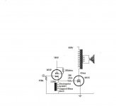
My implementation will be almost as simple, but my question at the moment is, how do you hook up the beam plates on a 6HV5A? There is no internal dedicated connection, they just get brought out to the pins. And yeah, if you are running with a plate voltage as low as 600V, you need to drive the grid postive to get any current, if the curves on the 6HS5 are anything like the 6HV5. I was trying to avoid positive grid drive, though I admit the lower plate voltage would make my mind rest a little easier. At 1kV+, the stored energy in the filter caps gets really, really deadly.
At any rate, I'm going to finish my other amp before thinking too hard about this one, or I'll never get anything done. It would be nice to figure out how to hook up the beam plates properly though....
At any rate, I'm going to finish my other amp before thinking too hard about this one, or I'll never get anything done. It would be nice to figure out how to hook up the beam plates properly though....
Well duh, I answered my own question just looking a little closer at the data sheet. The beam plates are connected to the cathode at the socket. I bet you can get all kinds of antisocial behavior if you hook them up in a roundabout fashion... I also took a peek at the 6HS5 specs at tubedata.org and it looks pretty similar to the 6HV5A, though the Sylvania data sheet there didn't have any curves.
I tied the beam to the cathode, pins 3,4 10 tied together. Kind of surprised me when I checked since I would have been tempted to tie them to the plate whatever the data sheet said. I expect I probably did this at some time but I must have prefered everything to the cathode. By the way I'm using a 10K output trans.
Matt
Matt
I would guess at I'm getting around 8 watts or so. As to sound, A2 amps sound different but I don't really know how to describe it, looser. So much of an amp's sound is quality of iron that its hard to go further than that.
If you have the parts needed I think it is very well worth building and having a listen yourself. If you don't like what you hear give A2 a try, you can use the primary of an unused output trans to stand the cathode driver on without having to use a neg. supply. That makes it simple. But I suggest using a bench supply for B+ as plate current is hard to predict without good positive grid plate curves. So you will need to watch things as you dial plate current up.
Matt
I don't mind negative supplies - the ones I use are small enough to fit nicely under the chassis, out of sight. I would tend to shy away from using choke loading, as the amp will be bulky and heavy enough without the extra iron. I don't have any extra iron to spare anyway - any dollars I spend in that direction will go to output transformers.
I also have no problem with characterizing the 6HV5A for positive drive if I decide to go there. I just finished doing a set of curves for a screen driven 6CD6GA to determine what I need for bias. Using that basic setup, all I'd need to do would be to wire up another socket and go to town... If I end up doing this, I'll post the curves just like I did for the 6CD6GA.
I also have no problem with characterizing the 6HV5A for positive drive if I decide to go there. I just finished doing a set of curves for a screen driven 6CD6GA to determine what I need for bias. Using that basic setup, all I'd need to do would be to wire up another socket and go to town... If I end up doing this, I'll post the curves just like I did for the 6CD6GA.
The high voltage and high current capability of the 6HV5A, along with its 35W plate dissipation may make it possible to get a lot of power out of a Class A setup if the output iron and power supplies are willing. I did a few numbers based on using the tube at 560V or 1120V B+ (a 400V secondary with full bridge or doubler), and was astonished at the results. However, a lot will depend on the current capability of the tube at the lower plate voltages (100-200V). with positive grid drive. A rarallel pair of these might be able to do awesome things with the higher plate voltage, even if they aren't biased and driven all the way. Time and effort will tell. If someone wants to nip in and scoop me on this, feel free - I'm still working on my screen driven sweep tube SE amp with cheap Hammond output transformers.
Maybee 6C33?or?is there any output tubes that have high mu, run at low plate voltage and higher current...
The 6HV5A this thread is about has a mu of 300, which makes a 12AX7 look like it's struggling. In a different context a 211 is considered a hi-mu tube with its mu of 12. So if you can make any further suggestion about the mu, plate voltage and current constraints you have in mind maybe someone will have a suggestion.
Matt
Matt
how about?
looking to just use a cathode follower direct coupled to output tube...similar to schematic posted.
problem is i do not want to build a 600v power supply... maybe a 300-400vdc power supply.
output tube could be: triode, pentode, tetrode, S.E., U.L. etc... i don't really care except it is Class A SE.
paralleling output tubes is ok too... as i will dc the input buffer to them.
ending up with a low impedance output transformer would be ideal to allow for wide BW.
I guess it could be positive grid bias, 0v grid bias, or negative grid bias....
Thanks!
You want high gain, high transconductance, and high current capability at low voltage in one package. The 6HV5A and related tubes look to be special cases that need high plate voltage to realize their true potential. If you want to operate at lower voltage, you may be stuck with a pentode of some sort, but I kinda doubt you'll get enough single stage gain so that you can operate with just a cathode follower input, unless you want to settle for low output power. The 6C33 is not a contender because of its low gain.
What I would do first is to calculate the peak voltage and current desired into your chosen load. Work back through the turns ratio of your chosen transformer, and that will tell you voltage and current swing at the plate. This will the capabilities you need for your output tube. If you choose too low of a plate voltage, you'll hamstring yourself in terms of output voltage swing, as even the best of tubes won't pull down near zero like a semiconductor.
What I would do first is to calculate the peak voltage and current desired into your chosen load. Work back through the turns ratio of your chosen transformer, and that will tell you voltage and current swing at the plate. This will the capabilities you need for your output tube. If you choose too low of a plate voltage, you'll hamstring yourself in terms of output voltage swing, as even the best of tubes won't pull down near zero like a semiconductor.
Well, this 6HV5 effort is a bit of perversity on my part. This familiy of beam triodes is an odd bunch, and it would be interesting to see what can be wrung out of them. I plan to use local feedbck to tame some of the gain. It's the prudent thing to do, elsewise I may have the FCC on my tail for operating an unlicensed transmitter...
Thomas Mayer had some spud amps (driving mids/highs I think) using 6HS5 beam triodes and 1200V B+ at EFT.05. There's a photo here: http://www.vinylsavor.de/etfamp.jpg
I think he was driving them from a very low-Z source (600 ohm environment).
It sounded very good...
Pete
I think he was driving them from a very low-Z source (600 ohm environment).
It sounded very good...
Pete
The king of Mu has to be the 6BK4. Mu of 2000, to bad it is totally useless for audio (I tried).
I tried an experiment once, that may be useful. Take a sweep tube and tie G1 and G2 together. This becomes the control grid. The result is a high Mu beam triode. Some tubes are more linear than others with this connection. They must operate in the positive grid region at normal plate voltages. Svetlana used to have curves for this mode on their web site. Curves for this mode (called High Mu mode) were published for some WWII era pentode transmitting tubes. Common audio pentodes (6L6, EL-34, KT-88 and others) are not linear enough.
I tried an experiment once, that may be useful. Take a sweep tube and tie G1 and G2 together. This becomes the control grid. The result is a high Mu beam triode. Some tubes are more linear than others with this connection. They must operate in the positive grid region at normal plate voltages. Svetlana used to have curves for this mode on their web site. Curves for this mode (called High Mu mode) were published for some WWII era pentode transmitting tubes. Common audio pentodes (6L6, EL-34, KT-88 and others) are not linear enough.
- Status
- This old topic is closed. If you want to reopen this topic, contact a moderator using the "Report Post" button.
- Home
- Amplifiers
- Tubes / Valves
- 6HV5A Single Ended Amp