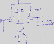
I am working on a P-P 7189 amp, class A (probably around 275v/10k load... haven't decided yet) and I want to rig up a simple-as-possible CCS phase inverter. Since the drive requirements for the 7189's are so low, a 12ax7 LTP should be fine to drive them from a line level input, so I don't have a driver stage to return feedback to. I drew up this inverter and wanted someone to check it out. I returned the feedback to the non-inverting grid. Simulations looked OK, but I want some opinions/ other options options before I breadboard.
Thanx
Thanx
Attachments
hacknet said:i always find 12ax7s failling to sound dynamic when forced to swing more than a couple volts. why not try some tube like the 5687 that is more fit for this role?
Only because I have a pile of 12ax7's around. If the design ends up being sound, I'll probably redesign around a better tube.
Does the circuit itself look good? I could always readjust the plate resistors and CCS for a different tube later.
Does the circuit itself look good?
Yes, apart from one thing - the CCS needs a bit of headroom. You need either to povide a negative rail (say -35v) for the CCS or to bias the LTP above ground.
The second method can be achieved by connecting the grounded grid to a potential divider from B+ to ground, with a cap of ~0.33uF from that grid to ground, in series with your feedback resistor (which can be smaller than you have shown here - say 1k). You need a 1Meg resistor between the grids, instead of from grid of the left half of the LTP to ground.
It can also be achieved by dierect coupling from the previous stage (if there is one). You will still need the bypass cap and feedback resistor on the grounded grid and the 1Meg resistor between the grids.
ray_moth said:
Yes, apart from one thing - the CCS needs a bit of headroom. You need either to povide a negative rail (say -35v) for the CCS or to bias the LTP above ground.
So the -12v that I have it referenced it to is low? I can up that to -30v or more if I have to. The fet I had is only rated at 25v, but that's no biggie. How do I calculate for that required headroom there?
The second method can be achieved by connecting the grounded grid to a potential divider from B+ to ground, with a cap of ~0.33uF from that grid to ground, in series with your feedback resistor (which can be smaller than you have shown here - say 1k). You need a 1Meg resistor between the grids, instead of from grid of the left half of the LTP to ground.
I have used that method too... I am just trying to keep this PI as simple as possible, going for a minimalistic thing.
It can also be achieved by dierect coupling from the previous stage (if there is one). You will still need the bypass cap and feedback resistor on the grounded grid and the 1Meg resistor between the grids.
No previous stage, so that doesn't work out.
Re: sorry
That looks pretty simple. What is the theory behind biasing the transistor to the junction of the 1M resistors? Do I need to generate a negative rail there as well?
Nafty said:See if that one is usefull to you:
That looks pretty simple. What is the theory behind biasing the transistor to the junction of the 1M resistors? Do I need to generate a negative rail there as well?
simple.
This diff pair can work with only one input.
The 1M resistors are error detector and at same time they pull the transistor on wich provide current to the diff pair. See that if any ac in the midle of the two resistors, is considered error and compensated on the cathode current.
You may use NFb or just ground the second grid.
NO -V requiered.
Regards.
Nafty
OBS: 3.6, are Kilos.
Re: simple.
Thank you. I'll give it a try. Any suggestions on transistors?
Nafty said:This diff pair can work with only one input.
The 1M resistors are error detector and at same time they pull the transistor on wich provide current to the diff pair. See that if any ac in the midle of the two resistors, is considered error and compensated on the cathode current.
You may use NFb or just ground the second grid.
NO -V requiered.
Regards.
Nafty
OBS: 3.6, are Kilos.
Thank you. I'll give it a try. Any suggestions on transistors?
Re: phase split
Cool. I don't have any BC639 on hand, so I'll give it a try with a MPSA06 or maybe even a MPS3904 just to see if I like the circuit.
tried out the FET circuit that I posted at the top, using a -25v negative rail on the source and it worked pretty well, so I am interested to try it against this circuit.
Nafty said:I think that you should try it.
Transistor....any BC639 or so.
It works just fine on mine.
Rgds.
Nafty
Cool. I don't have any BC639 on hand, so I'll give it a try with a MPSA06 or maybe even a MPS3904 just to see if I like the circuit.
tried out the FET circuit that I posted at the top, using a -25v negative rail on the source and it worked pretty well, so I am interested to try it against this circuit.
Re: phase spliter
HA! Thanx. I'll tell the cat to be careful. He usually runs to hide when he heard a power switch turn on since I have a nasty habit of applying the wrong polarity of global feedback and starting each project with a wicked oscillating howl.Nafty said:Hello Aletheian
It works and it is very taff and very stable. However, I've done lots of variations out of it. With time I'll draw it for you.
Dont frie the cat.
Nafty
I tried out the circuit with an MPSA06, and it worked very well. I imagine that I could improve it a bit more with a better BJT. I also tried a similar circuit but with a cascoded CCS, and that worked well too... a little bit more in the highs it seemed, but maybe I was imagining it.
I readjusted for a 12ax7, and a 12AT7 and tried it again... YUCK! There was a staggering loss of high end. A little NFB improved it, but the 12au7 had the best extension of any of them in this context, and just enough gain to drive the output tubes.
I readjusted for a 12ax7, and a 12AT7 and tried it again... YUCK! There was a staggering loss of high end. A little NFB improved it, but the 12au7 had the best extension of any of them in this context, and just enough gain to drive the output tubes.
Re: splitting those phases
Yes, I liked it. Thanx. It did the job, was simple to build, was sonically transparent and It worked well wth a 12au7. With a 12ax7... less so, but I didn't expect the 'ax7 version to sound all that good. I couldn't get enough drive to get the EL84's up to full blast if I applied NFB, but it was fine with no feedback.
I also tried a few more CCS topologies just for comparison, and I am heating up the iron right now to try another... actually, it is a hybrid of your scheme in cascode with a PNP transistor. After that, I'll try LED's in place of resistors ans listen again.
Nafty said:
Aletheian, have you any report for the audience?
Yes, I liked it. Thanx. It did the job, was simple to build, was sonically transparent and It worked well wth a 12au7. With a 12ax7... less so, but I didn't expect the 'ax7 version to sound all that good. I couldn't get enough drive to get the EL84's up to full blast if I applied NFB, but it was fine with no feedback.
I also tried a few more CCS topologies just for comparison, and I am heating up the iron right now to try another... actually, it is a hybrid of your scheme in cascode with a PNP transistor. After that, I'll try LED's in place of resistors ans listen again.
- Status
- This old topic is closed. If you want to reopen this topic, contact a moderator using the "Report Post" button.
- Home
- Amplifiers
- Tubes / Valves
- Help with inverter CCS+NFB