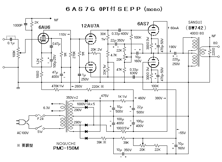
Anyone ever try them in SE ?
Ive been thinking of it. maybe parallel one 6080 per channel..
I kind of want to run them around 300v so I dont need an OPT with too heavy of a primary.. but i cant find graphs that go above 250v..
ah.. ill think of something. I suppose I could always make a OTL.
Ive been thinking of it. maybe parallel one 6080 per channel..
I kind of want to run them around 300v so I dont need an OPT with too heavy of a primary.. but i cant find graphs that go above 250v..
ah.. ill think of something. I suppose I could always make a OTL.
Brett said:Are these really the best tubes to use in a SET? They're not exactly linear.
Cheers
Well, they are the only power triodes ive got for the time being.
I'll probably just end up OTL-izing them.
6080
Hi,
And by doing so they'll end as as linear as toy can get:straight lines evenly spaced.
Cherio,
P.S.Sorry Brett.
Hi,
I'll probably just end up OTL-izing them.
And by doing so they'll end as as linear as toy can get:straight lines evenly spaced.
Cherio,
P.S.Sorry Brett.
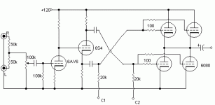
I threw together this mono one really quick.
i guess 16ohm+ output.
too tired to pick values for the resistors on the gain and cathodyne right now. I suppose i should have feedback too..
I got 2 big power transistors.. 500v 10a NPN.. can i get a bias supply with it?? im not too hot with SS.
i guess i need.. what.. 0-80v, and 0 to -80v. off a ±120v supply.
I should probably just buy some higher wattage pots..
Attachments
FROM A GLANCE.
Hi Colt45,
Any reason why you stack the tubes at the output stage like that?
When you look at the signal's phase at the output you will see that it will result in a near cancellation.
Unless of course I'm missing something.
Best to take it from a separate winding say something like 0-65 V
After full wave rectification you'll still have ~90V left which should be more than ample.
Cheers,
Hi Colt45,
Any reason why you stack the tubes at the output stage like that?
When you look at the signal's phase at the output you will see that it will result in a near cancellation.
Unless of course I'm missing something.

guess i need.. what.. 0-80v, and 0 to -80v. off a ±120v supply.
Best to take it from a separate winding say something like 0-65 V
After full wave rectification you'll still have ~90V left which should be more than ample.
Cheers,
I better bump the B+ on the gain and cathodyne... or I wont get enough drive.
thats the "enhanced futterman" or whatever you call it..
except it normally uses a split supply (±60v, ±90v, whatever) using positive on top, negative on the bottom.. and no output cap.
If I can figure out some kind of regulation then perhaps i should do split supply.
thats the "enhanced futterman" or whatever you call it..
except it normally uses a split supply (±60v, ±90v, whatever) using positive on top, negative on the bottom.. and no output cap.
If I can figure out some kind of regulation then perhaps i should do split supply.
OTL
Hi,
Yes,do.
And why you want to cross your output of the splitter is beyond me too.
See what I said above already.
Julius,where are you?
Seriously,if you want this to work you can use a Futterman as a basis,he put in some clever tricks but you don't need those in DIY.
While you're at it why not improve it in the process?
Cheers,
Hi,
I better bump the B+ on the gain and cathodyne... or I wont get enough drive.
Yes,do.
And why you want to cross your output of the splitter is beyond me too.
See what I said above already.
thats the "enhanced futterman" or whatever you call it..
Julius,where are you?
Seriously,if you want this to work you can use a Futterman as a basis,he put in some clever tricks but you don't need those in DIY.
While you're at it why not improve it in the process?
Cheers,
- Status
- This old topic is closed. If you want to reopen this topic, contact a moderator using the "Report Post" button.
- Home
- Amplifiers
- Tubes / Valves
- 6080/6AS7/6H13C/6H5C in SE?

