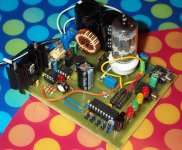
SMPS & tube pre-amp development board.
I posted pictures, circuit, and schematic for my first attempt at a SMPS/tube preamp at instructables:
LINK
http://www.instructables.com/ex/i/D4D58E3811D11029BE05001143E7E506/
Thanks to everyone who answered my questions about switching the tube heater.
Cheers,
Ian
I posted pictures, circuit, and schematic for my first attempt at a SMPS/tube preamp at instructables:
LINK
http://www.instructables.com/ex/i/D4D58E3811D11029BE05001143E7E506/
Thanks to everyone who answered my questions about switching the tube heater.
Cheers,
Ian
Attachments
I'm slightly puzzled as to why you use a PIC & FET driver to make an SMPS when there are several appropriate single chip specialist SMPS devices around that give you all sorts of stuff, such as very high performance (I get approx 88% efficiency), current limiting, HV shutoff etc. for very very little cost. The EMI/RFI is also easy to control - I use a variety of HP & Tek test kit to check my amps' performance, and removing SMPS artifacts (however you make the SMPS) is non-trivial, but can be done by using high switching frequencies, and careful control of artifacts on the supply rails, using shielded inductors and management of the grond plane.
For small tube/valve projects, my preferred chip is a MAX1771:
MAX1771 Nixie/Valve PSU.
The above link was originally done as a Nixie PSU a few years back but is widely used by valve/tube radio enthusiasts as a battery eliminator - I didn't use the Maxim app note as it didn't actually save any chips or components, as to drive the FET properly you need a specialist driver device - a PIC or an AVR doesn't have I/O ports that are "stiff" enough to get decent efficiency directly driving a FET, and there are capacitively induced currents in the FET gate that can & will damage the MCU's I/O ports. This is why LT,Maxim et al make specialist SMPS chips...
Its easy to make an SMPS, but getting one to do the best possible job is tricky.
I use the TC4427a fet driver from microchip.
Also: switching at higher frequencies is not always so straight forward. The coil charge and discharge time can be calculated. Frequencies beyond these limits don't use the coil to its fullest. Slower frequencies burn energy in the coil or fet. There is a "best frequency" for a given coil. The pic calculates this based on coil size and supply voltage. I have worked with the 1771 in the past. I just really lke having software control and not being locked into a certain vendor.
Also: switching at higher frequencies is not always so straight forward. The coil charge and discharge time can be calculated. Frequencies beyond these limits don't use the coil to its fullest. Slower frequencies burn energy in the coil or fet. There is a "best frequency" for a given coil. The pic calculates this based on coil size and supply voltage. I have worked with the 1771 in the past. I just really lke having software control and not being locked into a certain vendor.
- Status
- This old topic is closed. If you want to reopen this topic, contact a moderator using the "Report Post" button.